11
Outdoor Terminations - Horizontal Venting
Vent and combustion air intake terminations shall
be installed as depicted in
accordance with these instructions:
• Vent termination clearances must be consistent with the
NFGC, ANSI 2223.1/NFPA 54 and/or the CSA B149.1,
Natural Gas and Propane Installation Code.
• All minimum clearances must be maintained to protect
building materials from degradation by flue gases as
shown in
.
• Vent and combustion air intake terminations must
be located to ensure proper furnace operation and
conformance to applicable codes. The minimum distance
from any door, open window, or air gravity inlet is 1ft.
below, 1ft. horizontally, or 1ft. above. In Canada, CSA
B149.1 takes precedence over these instructions.
lists the necessary distances from the
vent termination to windows and building air intakes.
• The vent termination shall be located at least 4 ft.
horizontally from any electric meter, gas meter, regulator
and any relief equipment. These distances apply ONLY
to U.S. installations. In Canada, the Canadian Fuel Gas
Code takes precedence over these instructions.
• Do not install the vent terminal such that exhaust is
directed into window wells, stairwells, under decks
or into alcoves or similar recessed areas, and do not
terminate above any public walkways.
• If venting horizontally, a side wall vent kit is available
according to the pipe diameter size of the installation.
For 2 inch pipe use side wall vent kit #904617, and
for 3 inch pipe use kit #904349.
Please follow the
instructions provided with the kit.
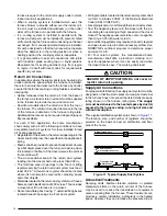
• When the vent pipe must exit an exterior wall close to
the grade or expected snow level where it is not possible
to obtain clearances shown in
, a riser may be
. Insulation
is required to prevent freezing of this section of pipe.
For vent freezing protection, see
.
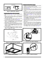
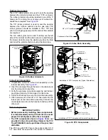
Figure 7
12” min.
to maximum
expected sno
w lev
el
(both pipes)
90° Elbo
w
Exhaust v
ent
option B
Exhaust v
ent
option A
Mounting kit f
aceplate
secured to w
all with scre
ws
(both pipes)
Comb
ustion
air inlet
Exhaust v
ent
option C
18” Min.
36” Max.
8” Min.
36” Max.
(all positions)
Figure 7.
Inlet & Exhaust Pipe Clearances
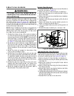
WARNING:
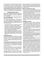
The combustion air vent and exhaust vent must
be configured as shown in Figure 9. Improper
vent terminations can cause the recirculation of
flue gases which may result in furnace vibration.
In severe cases, the furnace will cycle, due to
the intermittent contact between the flame and
the flame sensor. If you notice these oscillations
occurring, check the vent configuration to make
sure the exhaust vent does not have a 90 degree
termination.
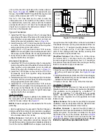
• For optimal performance, vent the furnace through a
wall that experiences the least exposure to winter winds.
• Termination kits consist of two face plates and an
insulating gasket to seal the exterior surface.
• The hole in the wall must be sized closely to the diameter
of the pipe.
• The pipe that penetrates the wall should be long enough
that it can be held in place by standard close fitting
couplings.
• Face plates are secured to both sides of the wall by the
couplings, and the gasket is retained against the wall
by the exterior face plate.
• Face plates must be fastened to the wall. Exterior face
plates must be flashed to prevent water infiltration.
If termination kits are not used, these requirements
must be followed:
• The hole size cut through the exterior wall is smaller
than the outside diameter of the couplings.
• The vent pipe extends through the wall approximately
1" and the gap between the wall and pipe is sealed.
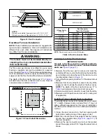
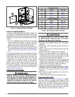
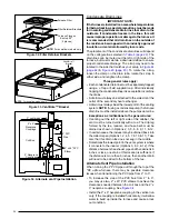
Figure 8. Vent Locations
12 in.
12 in.
4 ft.
Note 3
Less
than
10 ft.
3 ft.
NOTES:
1. All dimensions shown are minimum requirements.
2. Exterior vent terminations must be located at
least 12” above the maximum expected snow level.
3. Mechanical draft vent terminal
4. Direct vent terminal - more than 50,000 Btuh.
5. Direct vent terminal - less than 50,000 Btuh.
9 in.
4ft.
Forced
Air Inlet
Notes
2 & 4
Note 3
Notes
2 & 3
Notes
2 & 5
Figure 8
Содержание M4RC-072D-35C
Страница 47: ...47...


