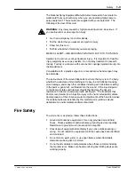
background image

Installation

3-6

Part 334598G03

E

 2008 Nordson Corporation

Securing the Hoses and Cables

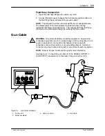
Gun Cable

S

Protect the end of the gun cable so that no contaminants, oils, particles,
or solvents are carried by it into the gun control unit receptacle.

S

Do not tie the cable to the machine members in areas where the cable
must move or stretch.

S

Do not bend the cable around a radius of less than 15.24 cm (6 in.) at

stationary points and 20.3 cm (8 in.) at flexing points.

S

Do not allow the cable to become abraded around sharp corners such
as booth edges.

S

Do not walk on the cable or run over it with heavy objects.

S

Do not use cable ties.  Use hook and loop tape to secure the cable.

S

Bundle the cable with the air and fluid hoses.

Air and Fluid Hoses

S

Bundle the air and fluid hose together with hook and loop tape, spiral-cut

tubing, or similar devices.  If you secure the hoses to a stationary object

at any point between the fluid delivery system, make sure the hoses can

flex without strain.

S

If desired, cover the spray gun, hoses, and other equipment in the spray
area with a grounded conductive wrapping to keep them clean.

Nozzle and Gasket with Restrictor Installation 

See Figure 3-5.

WARNING: 

 Shut off the gun control unit and ground the spray gun

electrode to remove any residual charge.  Failure to observe this warning

could result in personal injury.

WARNING: 

 Make sure the trigger lock is engaged, shut off the

fluid-delivery system, and relieve the fluid pressure in the system.  Failure to

observe this warning could result in an injection injury.

NOTE:  

Restrictors are devices that help atomize fluids.  They do not

normally reduce the fluid flow but tend to reduce pattern widths.
1. Turn off the gun control unit and ground the spray gun electrode to

remove any residual charge.

2. Point the spray gun into the booth or waste container and activate the

spray gun to relieve residual pressure.  Lock the trigger to prevent

inadvertent activation of the spray gun.

Содержание kinetix

Страница 1: ...34598G03 Issued 8 08 NORDSON CORPORATION AMHERST OHIO USA For parts and technical support call the Finishing Customer Support Center at 800 433 9319 Check http emanuals nordson com finishing for the latest version This document is subject to change without notice C APPROVED US FM ...

Страница 2: ...ight Original copyright date 2000 No part of this document may be photocopied reproduced or translated to another language without the prior written consent of Nordson Corporation The information contained in this publication is subject to change without notice Trademarks Cross Cut Kinetix Nordson and the Nordson logo are registered trademarks of Nordson Corporation Loctite is a registered tradema...

Страница 3: ...Description 2 2 Features 2 2 Options 2 2 Coating Materials 2 2 Theory of Operation 2 3 Electrostatic Charge 2 3 Fluid Flow 2 3 Air Flow 2 3 Installation 3 1 Preparation 3 1 Typical Airless System 3 2 Air and Fluid Hose Connections 3 3 Air Hose 3 3 Fluid Hose 3 3 Connecting the Fluid Hose 3 5 Gun Cable 3 5 Securing the Hoses and Cables 3 6 Gun Cable 3 6 Air and Fluid Hoses 3 6 Installing the Nozzle...

Страница 4: ...7 2 Nozzle Restrictor and Fluid Tip Replacement 7 2 Trigger Lock Replacement 7 4 Air Inlet Fitting Replacement 7 4 Ball Tip and Packing Cartridge Replacement 7 6 Preparation 7 6 Spray Gun Disassembly 7 6 Ball Tip and Packing Cartridge Removal 7 7 Ball Tip and Packing Cartridge Installation 7 9 Spray Gun Assembly 7 9 Air Valve Replacement 7 10 Back Cover Removal 7 10 Air Valve Removal 7 10 Air Valv...

Страница 5: ...cants 8 6 Recommended Kits 8 6 Perlastr Fluid Seal 8 6 Fluid Tip 8 6 Air Valve 8 6 Air Seal 8 7 Packing Cartridge 8 7 Trigger Lock 8 7 Optional Hotpaint Fluid Seal 8 8 Optional PTFE Packing Cartridge 8 8 Hoses and Tubing 8 8 Recommended Spare Parts 8 9 Specifications 9 1 Dimensions 9 1 Weight 9 1 Operating Pressures 9 1 Standard Fitting Sizes 9 1 Gun Electrostatics 9 2 Conductivity Range 9 2 Appro...

Страница 6: ...Table of Contents iv Part 334598G03 E 2008 Nordson Corporation ...

Страница 7: ...e familiar with all relevant safety rules and regulations and are physically capable of performing their assigned tasks Intended Use Use of Nordson equipment in ways other than those described in the documentation supplied with the equipment may result in injury to persons or damage to property Some examples of unintended use of equipment include S using incompatible materials S making unauthorize...

Страница 8: ... If you receive even a slight electrical shock shut down all electrical or electrostatic equipment immediately Do not restart the equipment until the problem has been identified and corrected S Obtain and read Material Safety Data Sheets MSDS for all materials used Follow the manufacturer s instructions for safe handling and use of materials and use recommended personal protection devices S Make s...

Страница 9: ...hit something on its way in and deflected causing more damage and many other variables including skin microflora residing in the paint or gun which are blasted into the wound If the injected paint contains acrylic latex and titanium dioxide that damage the tissue s resistance to infection bacterial growth will flourish The treatment that doctors recommend for an injection injury to the hand includ...

Страница 10: ...mation and advice Halogenated Hydrocarbon Solvent Hazards Do not use halogenated hydrocarbon solvents in a pressurized system that contains aluminum components Under pressure these solvents can react with aluminum and explode causing injury death or property damage Halogenated hydrocarbon solvents contain one or more of the following elements Element Symbol Prefix Fluorine F Fluoro Chlorine Cl Chl...

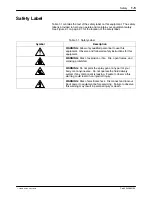
Страница 11: ... personnel to use this equipment Observe and follow all safety instructions for this equipment WARNING Risk of explosion or fire Fire open flames and smoking prohibited WARNING Do not point the spray gun at any part of your body or at anyone else Do not operate the fluid delivery system if any component is leaking Failure to observe this warning could result in an injection injury WARNING Risk of ...

Страница 12: ...Safety 1 6 Part 334598G03 E 2008 Nordson Corporation ...

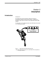
Страница 13: ...ings The spray gun is powered by a gun control unit and has a user replaceable internal voltage multiplier The spray gun is non circulating and can be used with heated and unheated non circulating spray systems WARNING Maximum Fluid Pressure 103 Bar 1500 PSI Figure 2 1 Kinetix Airless Manual Electrostatic Spray Gun Note Refer to Safety Label on page 1 5 for a description of the warning labels on t...

Страница 14: ...ble air assist air pressure and fluid flow rate S easy disassembly for cleaning and repair S low trigger force to reduce operator fatigue Options Options include a variety of Nordson Cross Cutr and dome nozzles restrictors fluid hoses and fittings Coating Materials The spray guns are compatible with a wide variety of coating materials including S general solvent based S metallics S high solids S m...

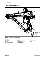
Страница 15: ...Flow Fluid enters the spray gun through a fluid supply hose 10 attached to the extension and flows to the fluid tip 2 The ball tip 14 opens as the trigger 12 is pulled allowing fluid to flow to the nozzle The packing cartridge 13 prevents fluid from flowing into the spray gun body and handle 7 Air Flow Activation trigger air 9 enters the spray gun through an inlet in the handle This air triggers a...

Страница 16: ... flow Air flow Fluid flow 8 11 2 3 1 5 6 Figure 2 2 Spray Gun Components and Operation 1 Electrode 2 Fluid tip 3 Multiplier 4 Extension 5 LED voltage indicator 6 kV actuator switch 7 Handle 8 Electrostatic cable 9 Activation trigger air 10 Fluid supply hose 11 Trigger lock 12 Trigger 13 Packing cartridge 14 Ball tip ...

Страница 17: ...asket with restrictor and the PTFE retaining washer are required For assistance in selecting the appropriate nozzle and restrictor for your application contact your Nordson Corporation representative Before installation S make sure you have the appropriate nozzle gasket or gasket with restrictor electrode and PTFE retaining washer for your application S make sure you have high pressure fluid hoses...

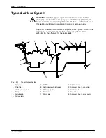
Страница 18: ...ury Figure 3 1 shows the components of a typical airless system Some of the components shown are optional Make sure your system contains self relieving shutoff valves for the fluid supply 1 2 3 4 5 6 7 8 12 11 14 13 16 15 10 9 Figure 3 1 Typical Airless System 1 Spray gun 2 Fluid filter 3 Heater as required 4 Pump 5 Air lubricator 6 Air regulator 7 Air filter 8 Self relieving shutoff valve 9 Fluid...

Страница 19: ...or sparking that could cause a fire Resistance checks from hose fitting to hose fitting should be a part of your regular maintenance procedures As coating materials become more conductive lower resistivity more current will bleed back through the fluid column in the fluid hose to the grounded fitting With a very conductive material like water all of the current will bleed to the ground and the spr...

Страница 20: ...B to D scale NOTE Readings outside these ranges are often acceptable MEG OHM METER A B E D F Non polar Non conductive Polar Conductive C PAINT RESISTIVITY METER LOW HIGH Figure 3 2 Resistivity Range for Coatings Current Draw Through a One Foot Length of 0 25 in ID Fluid Tube vs Coating Resistivity 0 20 40 60 80 100 120 0 0 1 0 2 0 3 0 4 0 5 0 6 0 7 Coating Resistivity Megohms Current Draw micro Am...

Страница 21: ...trostatic charge by isolating the fluid column Gun Cable WARNING Ground all electrically conductive equipment Ungrounded conductive equipment can store a static charge which could ignite a fire or cause an explosion if a hot spark is discharged Wear shoes with conductive soles such as leather or use grounding straps to maintain a connection to ground when working with or around electrostatic equip...

Страница 22: ...ationary object at any point between the fluid delivery system make sure the hoses can flex without strain S If desired cover the spray gun hoses and other equipment in the spray area with a grounded conductive wrapping to keep them clean Nozzle and Gasket with Restrictor Installation See Figure 3 5 WARNING Shut off the gun control unit and ground the spray gun electrode to remove any residual cha...

Страница 23: ...sket with Restrictor Installation 1 Fluid tip 2 PTFE retaining washer 3 Gasket or gasket with restrictor 4 Nozzle 5 Airless cap 6 Retaining ring 7 Electrode 6 Align the slot in the nozzle with the tab in the airless cap Make sure to line up the holes for the electrode 7 7 Insert the electrode though the nozzle and airless cap making sure the short leg of the electrode is inserted into the second h...

Страница 24: ...Installation 3 8 Part 334598G03 E 2008 Nordson Corporation ...

Страница 25: ...nded Wear electrically conductive gloves or a grounding strap connected to the gun handle or other true earth ground Do not wear or carry metallic objects such as jewelry or tools WARNING High pressure fluids are extremely hazardous Do not point the spray gun at any part of your body or at anyone else Do not operate the fluid delivery system if any component is leaking Failure to observe this warn...

Страница 26: ...en starting a new spray system for the first time flush the fluid delivery system hose and spray gun with a solvent compatible with the coating material to be used Remove the cap from the spray gun before flushing solvent through the spray gun Flushing will remove contaminants from the system 1 Turn on the air supply shutoff valve Adjust the air pressure to 1 03 bar 15 psi minimum This air supply ...

Страница 27: ...mation Spray Pattern and Atomization Adjustments Obtaining the correct spray pattern coating material atomization and transfer efficiency for your application requires a combination of operator experience and experimentation To obtain the best results perform the following tasks WARNING Shut off the power supply Ground the spray gun s electrode to remove any residual charge Failure to observe this...

Страница 28: ...th a clean cloth dampened with a compatible solvent Long Term 1 Shut off the power supply 2 Shut off the fluid delivery system 3 Trigger the spray gun into a waste container to relieve system fluid and air pressures 4 Remove the nozzle gasket or gasket with restrictor electrode and PTFE retaining washer 5 Flush the fluid delivery system fluid hose s and spray gun with a compatible solvent Refer to...

Страница 29: ...y gun electrode to remove any residual charge Failure to observe this warning could result in personal injury WARNING Shut off the fluid delivery system and relieve the fluid pressure in the system Failure to observe this warning could result in an injection injury Perform the following procedure at the end of each work shift 1 Shut down the fluid delivery system and relieve all fluid and air pres...

Страница 30: ...brush d Examine the nozzle and restrictor orifices with a magnifying lens If the orifices are clogged use a broach or probe to clean them Insert the broach or probe against the direction of flow Do not use a twisting or sawing motion to clean the orifices e Blow out the orifices with an OSHA approved blowgun against the direction of fluid flow 5 Clean the fluid tip and extension with a soft bristl...

Страница 31: ...ressurized solvents Spraying with pressurized solvents can force the solvent into spray gun cavities potentially damaging spray gun components System Flushing 1 Relieve system fluid pressure 2 Turn off the gun control unit and ground the spray gun electrode to remove any residual charge 3 Point the spray gun down into a grounded waste container Trigger the spray gun to drain the spray gun and hose...

Страница 32: ...h a compatible cleaning solvent NOTE Pointing the spray gun down at a slight angle will prevent solvents from entering the air passages and possibly damaging the air seals Most air seals are not universally compatible with all solvents and can be damaged 4 Dampen a soft cloth with a compatible cleaning solvent Point the spray gun downward and clean the exterior NOTE Take special care when cleaning...

Страница 33: ... ensure that the operator electrostatic spray gun electrostatic power supply and all conductive material within the spray area are connected to a true earth ground Proper grounding is essential for efficient operation and prevention of a buildup and subsequent discharge of an electrostatic charge that could ignite combustible material within the spray area Make sure the electrostatic equipment has...

Страница 34: ...Maintenance 5 6 Part 334598G03 E 2008 Nordson Corporation ...

Страница 35: ...un electrode to remove any residual charge Failure to observe this warning could result in personal injury These procedures cover only the most common problems that you may encounter If you cannot solve the problem with the information given here contact your local Nordson representative for help This section contains troubleshooting procedures for S common spray gun problems S spray pattern and f...

Страница 36: ...fluid flow Fluid delivery system malfunction Check the fluid delivery system air and fluid Blockage within spray gun fluid hose or fluid system Flush the system If necessary repair or replace clogged or damaged components Low fluid pressure WARNING Do not exceed the maximum fluid pressure rating of 103 bar 1500 psi Failure to observe this warning may result in death or personal injury Slowly incre...

Страница 37: ... or spitting 1 Air in fluid line Check for air leaks in the system Fluid pressure too low Increase the fluid pressure 2 Irregular pattern 2 Partially clogged nozzle orifice Remove the nozzle and clean Worn or damaged nozzle Replace the nozzle 3 Tails in pattern 3 Fluid pressure too low Increase the fluid pressure 1 2 3 Figure 6 1 Common Spray Pattern Faults 1 Fluttering or spitting 2 Irregular pat...

Страница 38: ...un KV on off switch in off position Check the position of the kV on off switch Switch to the on position if necessary Damaged gun cable Check the continuity of the cable wires from pin to pin Replace the cable if any opens or shorts are found Refer to Gun Cable Continuity Check on page 6 6 Malfunctioning voltage multiplier Check the continuity and resistance of the multiplier with a megohmmeter fo...

Страница 39: ... worn or damaged Remove the air valve and inspect the sealing surface Replace the air valve if worn or damaged Multiplier Continuity and Resistance Check See Figure 6 2 The multiplier should measure 277 340 megohms at 500 volts 1 Connect the earth ground probe common end of the megohmmeter to the contact spring 2 2 Connect the other probe of the megohmmeter to one of the three pins 1 on the end of...

Страница 40: ... at the connector terminals listed in Table 6 1 NOTE If the continuity check fails make sure the kV on off switch is in the on position Table 6 1 Spray Gun Cable Continuity Check Control Unit Connector Spray Gun Connector Position 1 Open 2 2 Closed 3 3 Closed 4 1 Closed 5 Open 6 Bracket Closed 1 2 3 1 2 3 4 5 6 Figure 6 3 Gun Cable Continuity Check ...

Страница 41: ...from the repair instructions using unauthorized parts or making unathorized modifications can result in personal injury or death and or the loss of approvals by agencies such as Factory Mutual Research Corporation FM or the Canadian Standards Association CSA CAUTION Do not overtighten threaded parts Failure to observe this caution will result in equipment damage NOTE Tighten all fittings until snu...

Страница 42: ...alant PTFE based lubricant NOTE Refer to the Parts section for service kits and replacement parts A B C D Figure 7 1 Combination Tool A Screwdriver B Packing cartridge tool C Fluid tip tool D Hose tool Nozzle Restrictor and Fluid Tip Replacement See Figure 7 2 1 Turn off the gun control unit and ground the spray gun electrode to remove any residual charge 2 Flush the fluid delivery system hoses an...

Страница 43: ...h the O ring toward the rear of the fluid tip Lubricate the O ring with O ring grease CAUTION Do not overtighten threaded parts Failure to observe this caution will result in equipment damage 9 Pull the trigger all the way back to retract the ball tip Screw the new fluid tip in the extension Tighten the fluid tip snugly 10 Install the nozzle electrode PTFE retaining washer and gasket or gasket wit...

Страница 44: ...ock Replacement 19 Handle 26 Trigger lock 27 Pin Air Inlet Fitting Replacement 1 See Figure 7 4 Remove the screws 30 41 to remove the back cover 45 from the handle and ground bracket A 2 Remove the two screws 52 that attach the fluid hose fitting D to the ground bracket Remove the fluid hose from the ground bracket 3 Slowly pull the back cover away from the handle so you do not disconnect the cabl...

Страница 45: ...h the cables between the handle and the back cover as the back cover is tightened 6 Secure the bracket to the handle and back cover using the two screws 30 7 Secure the fluid hose within the ground bracket A with the two screws 52 8 Install the back cover using the three screws 41 41 30 C B 45 41 30 31 A 52 D Figure 7 4 Air Inlet Fitting Replacement 30 Screws 31 Air inlet fitting male connector 41...

Страница 46: ...ponent of the packing cartridge You must order the the ball tip separately Preparation 1 Turn off the gun control unit and ground the spray gun electrode to remove any residual charge 2 Flush the fluid delivery system hoses and spray gun 3 Turn off the fluid delivery system Relieve system fluid pressures 4 Point the spray gun into the booth or grounded container and activate it to relieve any resi...

Страница 47: ...cket head screws 9 Large face seal O ring 10 Multiplier 19 Handle 24 Puller 25 Packing cartridge fluid return spring 28 Pivot screws 29 Trigger 38 Face seal O rings 52 Screws A Ground bracket B Fluid hose fitting Ball Tip and Packing Cartridge Removal See Figure 7 6 1 Hold the the puller 24 by its flats and unscrew it from the pull shaft 20 2 Push the pull shaft forward and unscrew the packing car...

Страница 48: ...18 Packing cartridge 20 Pull shaft 22 Sleeve retainer 23 Packing cartridge retainer 24 Puller A Connecting wire B Puller fitting 7 Lubricate the packing cartridge O ring and back up ring with MagnaLube G or an equivalent PTFE based lubricant 8 Generously lubricate both ends of the packing cartridge wire with MagnaLube G or an equivalent PTFE based lubricant Push and pull the wire 40 50 times to wo...

Страница 49: ... of the packing cartridge retainer then screw the packing cartridge retainer into the extension 7 Push the pull shaft forward and tighten the packing cartridge retainer with the combination tool hand tight 8 Wipe off excess dielectric grease 9 Apply a removable threadlocking adhesive to the threads of the pull shaft and screw the puller onto the pull shaft Spray Gun Assembly See Figure 7 5 1 Make ...

Страница 50: ...ve immediately Back Cover Removal 1 See Figure 7 7 Remove the two screws 52 that attach the fluid hose fitting D to the ground bracket A Remove the fluid hose from the ground bracket 2 Remove the screws 30 41 to remove the back cover 45 from the handle and ground bracket 3 Slowly pull the back cover away from the handle so you do not disconnect the cable connector B from the multiplier connector C...

Страница 51: ... outward Carefully insert the stem into the stem bore and seat the U cup into the recess surrounding the stem bore c Remove the air valve stem Use the blunt end of a dowel with a larger diameter than the inside diameter of the U cup seal to press the seal into the bore Make sure the end of the dowel does not have sharp edges 36 51 41 48 49 50 30 30 41 41 B C 45 A 52 D Figure 7 7 Air Valve Replacem...

Страница 52: ...e back cover as the back cover is tightened 5 Secure the ground bracket A to the handle and back cover using the two screws 30 6 Secure the fluid hose fitting D within the ground bracket with the two screws 52 7 Install the back cover 45 using the three screws 41 Multiplier Replacement Multiplier Removal See Figure 7 8 1 Turn off the gun control unit and ground the spray gun electrode to remove an...

Страница 53: ...ires 7 Pull the multiplier 10 out of the spray gun handle 10 12 13 C 41 30 B A 45 41 19 30 14 D 11 Figure 7 8 Multiplier Replacement 10 Multiplier 11 Contact spring 12 Heat sink bracket 13 Screws 14 Screw 19 Handle 30 Screws 41 Screws 45 Back cover A Ground bracket B Cable connector C Multiplier connector D Dielectric grease ...

Страница 54: ...n the back of the handle CAUTION Be careful not to pinch the cable between the handle and the back cover as the back cover is tightened 8 Secure the bracket to the handle and back cover using the two screws 30 9 Secure the back cover 45 with the screws 41 Tighten the screws to 0 9 1 13 N m 8 10 in lb 10 Secure the fluid hose within the ground bracket A with the two screws Gun Cable Replacement See...

Страница 55: ... not to lose the washers or bend the actuator switch 41 30 35 34 33 C B 45 41 30 32 33 Inside View of Back Cover 35 A D 52 Figure 7 9 Gun Cable Replacement 30 Screws 32 Electrostatic cable 33 Actuator switch 34 Washers 35 Screws 41 Screws 45 Back cover 52 Screws A Ground Bracket B Cable connector C Multiplier connector D Fluid hose fitting ...

Страница 56: ...ndle and the back cover as the back cover is tightened 3 Secure the ground bracket A to the handle and back cover using the two screws 30 4 Secure the back cover using the screws 41 Tighten the screws to 0 9 1 13 N m 8 10 in lb 5 Secure the fluid hose fitting within the ground bracket A with the two screws 52 Fluid Supply Hose Replacement See Figure 7 10 Fluid Hose Removal 1 Turn off the gun contr...

Страница 57: ...oss Fluid Hose Installation 1 Clean the hose fittings 2 Inspect the O ring 16 on the end fitting Replace if necessary 3 Lubricate the O ring with O ring grease 4 Push the end fitting into the extension fluid inlet boss D 5 Screw the retaining nut C into the extension Do not overtighten 6 Install the fluid hose into the ground bracket A 7 Secure the fluid hose within the ground bracket with the two...

Страница 58: ...otes Use Figure 7 11 and Table 7 1 as a quick reference when repairing the spray gun 8 10 16 15 20 22 23 38 16 21 28 30 38 49 36 41 43 38 9 6 11 44 13 1 13 10 10 14 8 2 8 9 8 3 2 14 4 11 12 13 8 8 8 5 10 10 7 15 6 9 9 18 10 24 25 8 8 8 8 19 8 8 8 Figure 7 11 Spray Gun Service Notes ...

Страница 59: ...n bore 20 end of pull shaft 23 inside of packing cartridge retainer 24 the small outside diameter Generously apply MagnaLube G PTFE filled lubricant to these parts 9 18 20 44 Apply threadlocking adhesive to the threads of these items 10 10 11 18 20 21 Apply a liberal coat of dielectric grease to these areas 11 23 Apply a thin coat of dielectric grease to the threads of this item 12 22 Apply a thin...

Страница 60: ...Repair 7 20 Part 334598G03 E 2008 Nordson Corporation ...

Страница 61: ...on column gives the part name as well as its dimensions and other characteristics when appropriate Indentions show the relationships between assemblies subassemblies and parts S If you order the assembly items 1 and 2 will be included S If you order item 1 item 2 will be included S If you order item 2 you will receive item 2 only The number in the Quantity column is the quantity required per unit ...

Страница 62: ...c 1 13 981522 S SCREW pan 4 40 x 0 125 in slot zinc 2 14 982763 S MACHINE SCREW pan 8 32 x 0 375 in steel zinc 1 15 336636 S KIT ball tip assembly 1 D 16 336677 S O RING Perlast 0 25 x 0 375 x 0 063 in 2 B C E 17 105527 S SERVICE KIT ring backup quantity 4 1 E 18 S CARTRIDGE ASSEMBLY packing electrostatic 1 E 19 336380 S HANDLE machined Kinetix 1 20 336638 S SHAFT WITH STUD packing cartridge Kinet...

Страница 63: ...ordson Corporation 35 1 7 8 10 17 16 15 20 22 23 24 25 38 16 21 28 29 27 26 19 30 31 32 34 38 40 48 49 50 51 36 41 42 43 45 18 12 13 14 39 38 37 2 33 47 46 9 53 3 4 6 5 11 44 52 Figure 8 1 Kinetix Airless Manual Electrostatic Spray Gun ...

Страница 64: ...at 8 32 x 1 375 in 18 8 stainless steel 3 42 336377 S KNOB on off switch electrostatic 1 43 940090 S O RING Viton 0 208 in ID x 0 07 in wide brown 1 C 44 336378 S PIN knob on off electrostatic 1 45 336421 S COVER electrostatic airless molded 1 46 325755 S WASHER curved spring 0 49 x 0 331 in 1 47 986030 S RETAINING RING external 31 basic 1 48 1090742 S PLUG valve air trigger 0 688 in dia head 1 49...

Страница 65: ...ordson Corporation 35 1 7 8 10 17 16 15 20 22 23 24 25 38 16 21 28 29 27 26 19 30 31 32 34 38 40 48 49 50 51 36 41 42 43 45 18 12 13 14 39 38 37 2 33 47 46 9 53 3 4 6 5 11 44 52 Figure 8 1 Kinetix Airless Manual Electrostatic Spray Gun ...

Страница 66: ...KIT Perlast gun Kinetix 1 4 336569 S BACKUP RING conductive 0 39 in ID x 0 045 in thick cut 1 A 6 336678 S O RING Perlast 0 375 x 0 50 x 0 063 in 1 A 16 336677 S O RING Perlast 0 25 x 0 375 x 0 063 in 2 B NOTE A Used on the fluid tips B Used on the packing cartridge and fluid hose Fluid Tip Item Part Description Quantity Note 336560 FLUID TIP high pressure Kinetix 1 3 S TIP fluid high pressure ele...

Страница 67: ...TE A This O ring is not used with this spray gun NS Not Shown Packing Cartridge NOTE The Kinetix spray gun is shipped with the gold packing cartridge which is appropriate for most coating materials Use the optional PTFE packing cartridge 1089862 with harsh chemical solvents such as MEK Item Part Description Quantity Note 1089861 PACKING CARTRIDGE KIT gold Kinetix 1 16 336677 S O RING Perlast 0 25 ...

Страница 68: ...id tips B Used on the packing cartridge and fluid hose Optional PTFE Packing Cartridge NOTE The PTFE packing cartridge is available for use with harsh chemical solvents such as MEK Part Description Note 1089862 KIT cartridge packing Kinetix electrostatic PTFE S CARTRIDGE ASSEMBLY packing electrostatic S BACKUP RING single 1 4 x 3 8 in 336677 S O RING Perlast 0 25 x 0 375 x 0 063 in Hoses and Tubin...

Страница 69: ...igh pressure gun 12 pack 1 336676 SEAL WASHER KIT high pressure gun 100 pack 1 336462 CABLE Kinetix manual 50 ft 5 conductor standard 336466 CABLE Kinetix manual 100 ft 5 conductor optional 336384 ELECTRODE high pressure electrostatic 6 336505 MULTIPLIER KIT 93 kV Kinetix 1 336643 EXTENSION KIT Kinetix high pressure 1 336642 WRENCH Kinetix combination tool 1 227583 BAG cover Kinetix 6 C 247658 DIE...

Страница 70: ...Parts 8 10 Part 334598G03 E 2008 Nordson Corporation ...

Страница 71: ...ual spray gun 837 29 5 NOTE The spray gun weight includes the fluid and air fittings Operating Pressures Operating Pressures Metric English Maximum air input pressure 6 9 bar 100 psi Maximum fluid input pressure 103 bar 1500 psi Maximum fluid temperature 82 _C 180 _F NOTE Supply air must be particulate free 5 microns maximum and oil free Use coalescing type air filters Standard Fitting Sizes Spray...

Страница 72: ...han 50 A may affect spray pattern transfer efficiency and finish If the conductivity of your material causes excessive current draw changing to the longer hose may be necessary Conductivity Range For optimum electrostatics coating resistivity the conductivity range should be greater than 25 megohms cm Approvals This spray gun has met the requirements for CE and FM approval ...

Страница 73: ...0 II 2 G 1180 n of notified body ATEX surveillance II group II surface 2 category 2 apparatus G explosive atmospheres with caused by gas mists or vapours EEx 0 24 mJ type of protection gas group temperature class Ambient temperature 20 C to 40 C Hazardous area Categories according to 94 9 CE Directive Gas mists or vapours Zone 0 1 G Gas mists or vapours Zone 1 2 G Gas mists or vapours Zone 2 3 G 4...

Страница 74: ...Safety Note KINETIX TRILOGY ATEX Page 2 DOC13015B05 5 EXAMPLE OF APPLICATION This shows the applicators and how a typical system is configured ...

Страница 75: ...Safety Note KINETIX TRILOGY ATEX Page 3 DOC13015B05 ...

Страница 76: ...04 108 EC ATEX Directive 94 9 EC The conformity are under observance of the following standards or standards documents EN12100 1998 EN61000 6 2 2007 EN60079 0 2006 EN61000 6 3 2006 FM7260 1996 EN50050 2006 EN55011 2007 Type of protection II 2 G EEx 0 24 mJ Ambient temperature 20 C to 40 C EC type examination certificate n CESI 01ATEX 017 Milan Italy N of notified body ATEX surveillance 1180 Baseef...

Отзывы: