background image

4-3-2 (d) WHITE BALANCE ADJUSTMENT VERIFICATION

CONDITIONS

Scanning frequency:

68 kHz/85 Hz

Display image:

Back raster pattern

X-Y Coordinates:

x = 0.283 ± 0.02,
y = 0.

297

 ± 0.02

Raster Luminance

0.3 ~ 1ft-L

ABL Luminance

30 ± 1 ft-L

Brightness:

Cut-off

Contrast:

Maximum

1. Check whether the color coordinates of the

back raster satisfy the above spec.
If they do not, return to 4-3-2 (a) and readjust
all settings.

2. Display a full white pattern.

Note:

Do not touch the 

G_GAIN

controls.

3. Adjust the Contrast Control on the monitor so

that the luminance of the video is about 5 ft-L.

4. Check whether the white coordinates of the

video meet the above coordinates spec.

5. Adjust the Contrast Control again so that the

luminance of the video is about 20 ft-L.

6. Check whether the white coordinates of the

video satisfies the above spec.
If they do not, return to 4-3-2 (a) and readjust
all settings.

4-3-3 Color Adjustments for 6500K

4-3-3 (a) BACK RASTER COLOR ADJUSTMENT

CONDITIONS

Scanning frequency:

68 kHz/85 Hz

Display image:

Back raster pattern

Brightness:

Cut-off

Contrast:

Maximum

1. Select 

COLOR CHANNEL 2

to control the

color for 6500K.

2. Adjust the luminance of the back raster to

between 0.3 to 1.0 ft-L using the 

G_CUT

controls.

3. Click on the << or >> boxes next to 

R_CUT

and 

B_CUT 

to adjust the R-Bias to x = 0.313 ±

0.02 and the B-Bias to y = 0.329 ± 0.02.

4-3-3 (b) G-GAIN ADJUSTMENT

This procedure is the same as that for 9300K, refer
to the procedure on page 4-5.

4-3-3 (c) WHITE BALANCE ADJUSTMENT

CONDITIONS

Scanning frequency:

68 kHz/85 Hz

Display image:

Full white pattern

Brightness:

Cut-off

Contrast:

Maximum

1. Click on the << or >> boxes next to 

R_GAIN

and 

B_GAIN 

to make the video white.

(For 6500K color adjustment:
x = 0.313 ± 0.02, y = 0.329 ± 0.02.)

2. Refer to the procedure for 9300K, section 

4-3-2 (c) steps 2 and 3.

4-3-3 (d) WHITE BALANCE ADJUSTMENT VERIFICATION

Refer to the procedure for 9300K, section 4-3-2 (d).

4-3-4 Color Adjustments for 5000K

4-3-4 (a) BACK RASTER COLOR ADJUSTMENT

CONDITIONS

Scanning frequency:

68 kHz/85 Hz

Display image:

Back raster pattern

Brightness:

Cut-off

Contrast:

Maximum

1. Select 

COLOR CHANNEL 3

to control the

color for 5000K.

2. Adjust the luminance of the back raster to

between 0.3 to 1.0 ft-L using the 

G_CUT

controls.

3. Click on the << or >> boxes next to 

R_CUT

and 

B_CUT 

to adjust the R-Bias to x = 0.346 ±

0.02 and the B-Bias to y = 0.359 ± 0.02.

4-3-4 (b) G-GAIN ADJUSTMENT

This procedure is the same as that for 9300K, refer
to the procedure on page 4-5.
Adjust the brightness of the 

G_GAIN

less 5 ft-L

than brightness of procedure for 9300K.

4-3-4 (c) WHITE BALANCE ADJUSTMENT

CONDITIONS

Scanning frequency:

68 kHz/85 Hz

Display image:

Full white pattern

Brightness:

Cut-off

Contrast:

Maximum

1. Click on the << or >> boxes next to 

R_GAIN

and 

B_GAIN 

to make the video white.

(For 5000K color adjustment:
x = 0.346 ± 0.02, y = 0.359 ± 0.02.)

2. Refer to the procedure for 9300K, section 

4-3-2 (c) steps 2 and 3.

4 Alignment and Adjustments

4-6 

                    720C/920C

Содержание 720C

Страница 1: ...ifications 3 Disassembly Reassembly 4 Alignment Adjustments 5 Troubleshooting 6 Exploded View Parts List 7 Electrical Parts List 8 Block Diagram 9 Wiring Diagram 10 Schematic Diagrams BH68 00294B rev 2 Note Sections 6 8 9 and 10 are in hardcopy format in the printed supplement ...

Страница 2: ...ch lead dress to make certain that the leads are not pinched or that hardware is not lodged between the chassis and other metal parts in the monitor 2 Inspect all protective devices such as nonmetallic control knobs insulating materials cabinet backs adjustment and compartment covers or shields isolation resistor capacitor networks mechanical insulators etc 3 Leakage Current Hot Check Figure 1 1 W...

Страница 3: ...stance between each blade of the AC plug and accessible conductive parts see above should be greater than 1 megohm 7 Never defeat any of the B voltage interlocks Do not apply AC power to the unit or any of its assemblies unless all solid state heat sinks are correctly installed 8 Always connect a test instrumentÕs ground lead to the instrument chassis ground before connecting the positive lead alw...

Страница 4: ...ive Maximum Pixel Clock rate 17 19 205 MHz Active Display 17 Horizontal 310 mm 3 mm 12 2 0 12 Vertical 232 mm 3 mm 9 13 0 12 19 Horizontal 355 mm 3 mm 13 98 0 12 Vertical 266 mm 3 mm 10 47 0 12 Input Voltage AC 90 to 264 Volts 60 50 Hz 3 Hz Power Consumption max 17 120 Watt 19 135 Watt Dimensions Unit 17 16 3 x 16 9 x 17 2 Inches 415 0 x 430 3 x 438 mm W x D x H 19 18 4 x 19 6 x 19 0 Inches 468 0 ...

Страница 5: ...te 60 023 16 660 1 219 2 235 13 003 0 203 75 025 13 328 0 050 0 466 12 795 0 017 78 75 53 674 18 631 1 138 2 702 14 222 0 569 85 061 11 756 0 056 0 503 11 179 0 019 56 250 Positive Positive Separate 93 750 10 667 0 948 1 501 7 901 0 316 75 000 13 333 0 032 0 491 12 800 0 011 202 500 Positive Positive Separate Mode IBM VESA MAC Timing 68 677 14 561 1 016 2 201 10 836 0 508 84 997 11 765 0 044 0 524...

Страница 6: ... 1 5 Removing the Bottom Shield 1 Remove the 1 screw on the Bottom Shield Cover 2 Lift off the Bottom Shield 3 1 6 Removing the Video PCB Assembly 1 Remove the Video PCB from the CRT 2 Disconnect CN102 CN101 CN12 and CN13 on the Video PCB Assembly and Video PCB AssÕy from the CRT Neck 720C 920C 3 1 3 Disassembly and Reassembly This section of the service manual describes the disassembly and reasse...

Страница 7: ... H_DY CN604 and Anode Cap on the Main PCB Assembly 3 1 9 Removing the Main PCB 1 Remove 6 screws on the main PCB 2 Pull the Main PCB towards you and carefully lift out the main PCB and placet it on a flat level surface that is protected from static electricity 3 1 10 Removing the Bracket 1 Remove the 10 screws on the Front Cabinet 3 1 11 Removing the Degaussing Coil 1 Using pinch nosed pliers or l...

Страница 8: ...ical 50 Hz to 160 Hz Automatic Unless otherwise specified adjust at the 1024 x 768 mode H 68 kHz V 85 Hz signals Refer to Table 2 1 on pages 2 2 and 2 3 4 1 1 f HIGH VOLTAGE ADJUSTMENT Signal 1024 x 768 mode 68 kHz 85 Hz Display image Full white Contrast Maximum Brightness Maximum Limit 27 3 kV 0 5 kV 17Ó 26 kV 0 5 kV Measure the hight voltage level at the anode cap High voltage should be within t...

Страница 9: ...ed in 4 1 2 a above 2 Color analyzer or any luminance measurement equipment 4 1 3 Connecting the SoftJig Connect the monitor to the signal generator and or PC as illustrated in Figures 4 1 and 4 2 Note The signal cable connector which includes the 3 wire cable must connect to the monitor If you use Setup 2 PC only no signal generator you can only make adjustments to the signal timing available on ...

Страница 10: ...t to H_POSI to center the horizontal image on the raster 4 2 1 d VERTICAL POSITION ADJUSTMENT CONDITIONS Scanning frequency 91 kHz 85 Hz Display image Crosshatch pattern Brightness Cut off Contrast Maximum Click on the or box next to V_POSI to center the vertical image on the raster 4 2 2 Linearity Linearity affects the symmetry of images as they appear on the screen Unless each row or column of b...

Страница 11: ...trast Maximum Click on the or box next to PARALLEL to make the image area rectangular Figure 4 6 Parallelogram 4 2 6 Side Pincushion Adjustment CONDITIONS Scanning frequency 91 kHz 85 Hz Display image Crosshatch pattern Brightness Cut off Contrast Maximum Click on the or box next to BARREL to straighten the sides of the image area 4 2 7 Tilt Adjustment CONDITIONS Scanning Frequency 91 kHz 85 Hz Di...

Страница 12: ...set the ÒyÓ coordinate to 0 297 0 02 4 Click on the or box next to R_CUT to set the ÒxÓ coordinate to 0 283 0 02 Note If the above adjustments cannot be done to each coordinate click on the or box next to G_CUT to decrease or increase the green cutoff bias and repeat procedures 2 and 3 4 3 2 b G GAIN ADJUSTMENT Figure 4 8 Green Box Pattern CONDITIONS Scanning frequency 68 kHz 85 Hz Display image G...

Страница 13: ...NT This procedure is the same as that for 9300K refer to the procedure on page 4 5 4 3 3 c WHITE BALANCE ADJUSTMENT CONDITIONS Scanning frequency 68 kHz 85 Hz Display image Full white pattern Brightness Cut off Contrast Maximum 1 Click on the or boxes next to R_GAIN and B_GAIN to make the video white For 6500K color adjustment x 0 313 0 02 y 0 329 0 02 2 Refer to the procedure for 9300K section 4 ...

Страница 14: ...nning frequency 68 kHz 85 Hz Display image White flat field Luminance Cut off point at the center of the display area Note Color purity adjustments should only be attempted by qualified personnel PROCEDURE adjusting convergence For trained and experienced service technicians only Use the following procedure to correct minor color purity problems 1 Make sure the display is not affected by external ...

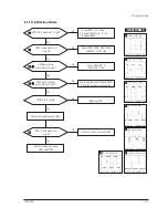
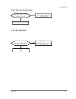
Страница 15: ...oltage develops but no raster appears Video output circuits High voltage does not develop Horizontal output circuits 5 1 1 No Power Supply Check and replace FG601 D601 IC661 IC662 Done Repeating start Check and replace D601 D604 D663 Q632 and Q664 No Yes IC601 Pin 1 waveform is right Check and replace IC601 IC602 IC604 Yes No IC602 and IC604 are right Replace parts and verify voltages Yes No Norma...

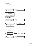
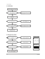
Страница 16: ... Failure Check signal source H V sync video level Make no H V sync power off mode LED blinks Check IC201 Pin 39 Yes No 12 V line off Check IC201 Pin 9 Yes No Q632 Base driving voltage exists Check IC201 Pin 10 Check and replace Q632 Yes No Done ...

Страница 17: ...5 Check DY connector connection Yes No IC261 Pin 4 is high Replace IC261 Check some parts around Q261 and Q262 Yes No IC261 Pin 26 waveform is right Check some parts around IC261 Yes No WAVEFORMS 2 3 4 5 6 8 7 3 230 V Q405 Source CH1 P P 230 V CH1 RMS 150 1 V 8 12 08 V IC261 26 CH1 P P 12 08 V CH1 RMS 7 396 V 2 10 96 V IC402 6 CH1 P P 10 96 V CH1 RMS 6 180 V 5 54 V Q404 Drain CH1 P P 54 V CH1 RMS ...

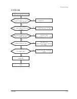
Страница 18: ... IC201 Pin 21 voltage varies with different H_Lin DAC values IC403 Pin 7 8 voltage varies with different H_Lin DAC values Check 12 V line Check some parts around IC403 Check L403 Yes Yes No Check and replace IC201 No Replace IC201 No 5 1 6 Invariable H_Size IC261 Pin 28 voltage varies with different H_Size DAC values IC401 Pin 6 output duty varies with different H_Size DAC values Check some parts ...

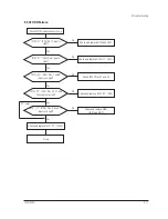
Страница 19: ...02 Pin 2 and IC201 Pin20 Yes No 5 1 8 Side Pin or Trap Failure IC261 Pin 24 output exists Yes Check and replace IC261 Check and replace IC402 Check some parts IC402 Pin 2 and IC261 Pin 24 5 1 9 Para or Pin Balance Failure IC261 Pin 24 output varies with different DAC values No Replace IC261 No WAVEFORMS 9 9 29 8 V T402 8 CH1 P P 29 8 V CH1 RMS 7 14 V ...

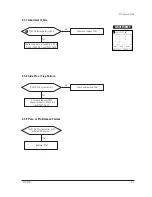
Страница 20: ... Check and replace CRT Yes Yes No Check and replace IC201 No Check tilt connector connection 5 1 11 V Deflection Failure 14 V line is on IC261 Pin 23 output exists Check and replace IC261 Yes Yes No Refer to 5 1 1 No Power Supply No IC301 Pin 1 input exists Check R276 and R304 Yes No IC301 Pin 6 output exists Check and replace some parts around IC301 Yes No Check V DY connector connection ...

Страница 21: ...261 Pin 23 output varies with different DAC values Yes Check some parts around IC301 Check bias voltage Check and replace IC261 and IC301 No 5 1 13 High Voltage Failure Q524 gate driving pulse exist Check 12 V line Check and replace Q521 Q522 Q523 Q524 and IC501 Yes No Done ...

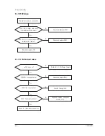
Страница 22: ...eck and replace IC103 17 IC04 Yes No Check and replace Q101 Q102 and 12 V line Check CN102 5 1 14 ABL Failure 5 1 15 Dynamic Focus Failure IC261 Pins 18 and 15 output are right Check and replace IC261 Yes No Some parts around Q551 Q552 Q553 and Q554 are right Replace failed part Yes No Some parts around T502 are right Replace failed part Check the connection between FBT Pin 13 CRT Socket PCB Yes N...

Страница 23: ...ck I2C bus and 12 V line Yes Yes No Check CN101 No IC102 Pins 4 6 and 14 17 IC105 Pin 1 3 5 outputs are right Check 12 V line Check and replace IC102 17 IC105 Yes No Cathode DC levels are right Check 80 V line Check and replace IC101 and IC104 17 IC104 Yes No G2 voltage is right Check G2 wire CRT Socket board and FBT Change CRT Yes Done No Check signal cable and connection ...

Страница 24: ...3 and 14 inputs are right Check X201 C204 and C205 Yes Yes No Check IC606 No IC201 Pin 18 input is right Check IC202 Yes No All in output values are right Replace IC201 Yes No Done 12 13 12 3 42 V IC201 33 CH1 P P 3 42 V CH1 RMS 2 500 V 13 3 16 V IC201 32 CH1 P P 3 16 V CH1 RMS 2 560 V WAVEFORMS ...

Страница 25: ...eck and replace D302 and Q301 No IC103 17 IC04 Pins 7 and 8 inputs are right Check IC201 Pins 41 and 42 Yes No IC103 17 IC04 Pins 20 21 and 22 outputs are right Check and replace IC103 17 IC04 Yes No IC101 17 IC104 Pins 4 9 and 13 inputs are right Check and replace QB51 QG51 and QR51 Check and replace IC101 17 IC104 Yes Done No Check CN102 and connector Ass y 17 only ...

Страница 26: ...output is right Check and replace IC201 Check user function key Yes No R217 and R630 are right Replace R217 and R630 Done Yes No Check degaussing connector 5 1 20 Degaussing Failure 5 1 19 User Control Failure IC201 Pins 35 and 36 inputs are right at each function Check and replace function key Check and replace IC201 Done Yes No Check connector Ass y ...

Страница 27: ...Check G2 voltage high voltage R G B cathode voltage Yes No No LED is Amber color No Yes 5 2 2 Shut down Yes 5 2 2 Shut Down Blinking LED s Scan failure Check horizontal vertical deflection system and check power supply secondary voltages No Yes Yes Check power supply No High voltage failure Check high voltage system Check and replace IC201 Done No Yes Video failure Check Video board No Yes ...

Страница 28: ...ltage on all cathodes Refer to 5 1 16 No Video Yes Yes No Check signal generator and cathode No Are proper DC voltage on all cathodes Check IC104 17 IC104 Pins 19 20 and 21 Pins 10 11 and 12 Check QB02 QB03 QG02 QG03 QR02 and QR03 Change the CRT Done Yes No Is G2 voltage right Check G2 wire G2 control volume and FBT Yes No ...

Страница 29: ...and FBT No Is blank pedestal on Pins 29 32 and 35 of IC101 17 25 28 30 of IC104 Check IC101 17 IC104 and related components Yes No Is V_FLB pulse on Pin 17 of IC103 17 IC04 Check Q301 Done Yes No Is blank pedestal on all cathodes Check Pins 24 25 and 26 of IC101 17 19 20 21 of IC104 Check QB02 QB03 QG02 QG03 QR02 and QR03 Yes No Check white balance adjustment 5 2 4 Visible Retrace ...

Страница 30: ...C1 are right Replace IC1 Yes Yes No Check Video cable No Signals at CN201 Pins 6 9 and CN102 Pin 6 are right Check wire dressing and connections Check circuits on Main board IC201 and IC261 Yes Done No Check input signals Pins 1 2 and 3 of D SUB connector 5 2 5 Unsynchronized Image ...

Страница 31: ...720C 920C 5 17 Is the convergence now within spec Readjust convergence No Done Yes Is the convergence now within spec Done Change CRT and readjust convergence No Done Yes Try readjusting convergence 5 2 6 Misconvergence ...

Страница 32: ...d check for focus change Yes Is dynamic focus circuit right Refer to 5 1 15 Dynamic Focus Failure Replace the CRT and verify focus Yes No Adjust focus VR 5 2 7 Poor Focus 5 2 8 Purity Failure Purity is right Degaussing circuit is right Refer to 5 1 20 Degaussing Failure Replace CRT and verify purity Yes No No Done Yes Degaussing ...

Страница 33: ...720C 920C 6 1 6 1 720C Exploded View and Parts List ...

Страница 34: ...720C 920C 6 2 6 2 920C Exploded View and Parts Lists ...

Страница 35: ...6 3x7 5 C202 2401 000486 C AL 10uF 20 50V GP TP 6 3x7mm 5 C203 2201 000119 C CERAMIC DISC 100nF 80 20 50V Y5V TP C204 2201 000247 C CERAMIC DISC 0 015nF 5 50V NP0 TP 5x3 C206 2401 000480 C AL 10uF 20 50V GP TP 5x11 5 C207 2202 002009 C CERAMIC MLC AXIAL 100nF 80 20 50V Y5 C208 2202 002008 C CERAMIC MLC AXIAL 10nF 80 20 50V Y5V C209 2202 002008 C CERAMIC MLC AXIAL 10nF 80 20 50V Y5V C210 2202 00200...

Страница 36: ... TP 5mm C285 2401 000597 C AL 1uF 20 50V GP TP 4x7mm 1 5mm C301 2401 003139 C AL 1000uF 20 25V WT TP 10 20 5mm C302 2202 002009 C CERAMIC MLC AXIAL 100nF 80 20 50V Y5 C305 2301 000010 C FILM PEF 100nF 5 100V TP 11 5x12 5mm C306 2401 000852 C AL 220uF 20 35V GP TP 8x11 5mm 5 C307 2301 000010 C FILM PEF 100nF 5 100V TP 11 5x12 5mm C308 2305 000237 C FILM MPEF 1uF 5 63V TP 7 5x15 5mm 5mm C310 2301 00...

Страница 37: ...00131 C FILM MPPF 150nF 5 250V TP 19x16x7 5 7 C457 2306 001011 C FILM MPPF 56nF 5 250V TP 19x7 5x14 5 C459 2401 003080 C AL 3 3UF 20 50V BP TP 5X11 2 5 C501 2301 001027 C FILM PEF 15nF 10 250V TP 9 5x12x4 5 5 C502 2201 000119 C CERAMIC DISC 100nF 80 20 50V Y5V TP C503 2401 000480 C AL 10uF 20 50V GP TP 5x11 5 C504 2401 001576 C AL 47uF 20 50V GP TP 8x11 5 5 C505 2401 000037 C AL 470uF 20 16V GP TP...

Страница 38: ...15 2301 000168 C FILM PEF 150nF 5 100V TP 11 5x19mm 7 C616 2401 000603 C AL 1uF 20 50V GP TP 5x11 5 C617 2301 000010 C FILM PEF 100nF 5 100V TP 11 5x12 5mm C633 2401 000010 C AL 220uF 20 16V GP 6 3x11mm 2 C634 2401 000042 C AL 100uF 20 16V GP TP 6 3x7 5 C635 2202 002008 C CERAMIC MLC AXIAL 10nF 80 20 50V Y5V C636 2401 003497 C AL 100uF 20 160V WT TP 12 5x25mm 5 C638 2401 003496 C AL 47uF 20 350V W...

Страница 39: ...200MA DO 35 D264 0401 000005 DIODE SWITCHING 1N4148 100V 200MA DO 35 D301 0402 000272 DIODE RECTIFIER UF4001 50V 1A DO 41 TP D302 0401 000005 DIODE SWITCHING 1N4148 100V 200MA DO 35 D401 0401 000005 DIODE SWITCHING 1N4148 100V 200MA DO 35 D402 0401 000005 DIODE SWITCHING 1N4148 100V 200MA DO 35 D403 0401 000005 DIODE SWITCHING 1N4148 100V 200MA DO 35 D405 0402 000274 DIODE RECTIFIER UF4004 400V 1A...

Страница 40: ...G 1N4148 100V 200MA DO 35 D632 0402 001289 DIODE RECTIFIER 31DF6 600V 3A DO 201AD B D633 0402 000250 DIODE RECTIFIER RG4C 1000V 1A D634 0402 001190 DIODE RECTIFIER RG10Z 200V 1 2A DO 15 TP D635 0402 001118 DIODE RECTIFIER UF1G 400V 1 2A DO 204AL D636 0402 000274 DIODE RECTIFIER UF4004 400V 1A DO 41 TP D637 0402 000016 DIODE RECTIFIER UF5404 400V 3A DO 201AD D638 0402 000274 DIODE RECTIFIER UF4004 ...

Страница 41: ...7A P C B MAIN PG FR1 247 330 1 6T POS601 1404 000002 THERMISTOR PTC 9ohm 20 TR RECT Q261 0501 000586 TR SMALLSIGNAL KSC945 NPN 250mW TO 92 TP Q262 0501 000303 TR SMALLSIGNAL KSA733 PNP 250mW TO 92 TP Q263 0501 000122 TR SMALLSIGNAL 2N3904 NPN 625mW TO 92 TP Q264 0505 000013 FET SILICON VN2222LL N 60V 150mA 7 5ohm Q290 0501 000586 TR SMALLSIGNAL KSC945 NPN 250mW TO 92 TP Q301 0501 000586 TR SMALLSI...

Страница 42: ... 5 1 8W AA TP 1 8X3 2MM R211 2001 000281 R CARBON 100OHM 5 1 8W AA TP 1 8X3 2MM R212 2001 000734 R CARBON 4 7KOHM 5 1 8W AA TP 1 8X3 2MM R214 2001 000515 R CARBON 220OHM 5 1 8W AA TP 1 8X3 2MM R215 2001 000869 R CARBON 56OHM 5 1 8W AA TP 1 8X3 2MM R216 2001 000869 R CARBON 56OHM 5 1 8W AA TP 1 8X3 2MM R217 2001 000281 R CARBON 100OHM 5 1 8W AA TP 1 8X3 2MM R218 2001 000281 R CARBON 100OHM 5 1 8W A...

Страница 43: ...8W AA TP 1 8X3 2MM R272 2001 000660 R CARBON 33KOHM 5 1 8W AA TP 1 8X3 2MM R273 2001 000563 R CARBON 27KOHM 5 1 8W AA TP 1 8X3 2MM R274 2001 000734 R CARBON 4 7KOHM 5 1 8W AA TP 1 8X3 2MM R275 2001 000273 R CARBON 100KOHM 5 1 8W AA TP 1 8X3 2MM R276 2001 000281 R CARBON 100OHM 5 1 8W AA TP 1 8X3 2MM R277 2001 000009 R CARBON 20KOHM 5 1 8W AA TP 1 8X3 2MM R278 2001 000734 R CARBON 4 7KOHM 5 1 8W AA...

Страница 44: ...W AA TP 2 4X6 4MM R402 2001 000645 R CARBON 330KOHM 5 1 8W AA TP 1 8X3 2MM R403 2001 000011 R CARBON 75KOHM 5 1 8W AA TP 1 8X3 2MM R404 2001 000563 R CARBON 27KOHM 5 1 8W AA TP 1 8X3 2MM R405 2003 000763 R METALOXIDE S 6 8ohm 5 3W AA TP 6x16m R406 2001 000006 R CARBON 2 4KOHM 5 1 8W AA TP 1 8X3 2MM R407 2001 000958 R CARBON 750OHM 5 1 8W AA TP 1 8X3 2MM R408 2001 000011 R CARBON 75KOHM 5 1 8W AA T...

Страница 45: ...HM 5 1 8W AA TP 1 8X3 2MM R464 2001 000273 R CARBON 100KOHM 5 1 8W AA TP 1 8X3 2MM R465 2001 000273 R CARBON 100KOHM 5 1 8W AA TP 1 8X3 2MM R466 2001 000429 R CARBON 1KOHM 5 1 8W AA TP 1 8X3 2MM R467 2001 000429 R CARBON 1KOHM 5 1 8W AA TP 1 8X3 2MM R468 2001 000429 R CARBON 1KOHM 5 1 8W AA TP 1 8X3 2MM R469 2001 000429 R CARBON 1KOHM 5 1 8W AA TP 1 8X3 2MM R470 2001 000429 R CARBON 1KOHM 5 1 8W A...

Страница 46: ...HM 5 1 2W AA TP 2 4X6 4 R553 2001 001153 R CARBON S 47OHM 5 1 2W AA TP 2 4X6 4M R554 2001 000734 R CARBON 4 7KOHM 5 1 8W AA TP 1 8X3 2MM R555 2001 000319 R CARBON 120KOHM 5 1 8W AA TP 1 8X3 2MM R556 2001 000045 R CARBON 1 8KOHM 5 1 4W AA TP 2 4X6 4MM R558 2003 000462 R METALOXIDE S 10Kohm 5 2W AA TP 4x12m R560 2001 000522 R CARBON 22KOHM 5 1 8W AA TP 1 8X3 2MM R561 2001 000890 R CARBON 6 8KOHM 5 1...

Страница 47: ...0OHM 5 1 8W AA TP 1 8X3 2MM R664 2001 000495 R CARBON 20KOHM 5 1 4W AA TP 2 4X6 4MM R665 2004 000964 R METAL 470Kohm 1 1 4W AA TP 2 4x6 4m R666 2004 000964 R METAL 470Kohm 1 1 4W AA TP 2 4x6 4m R667 2004 001211 R METAL 7 5Kohm 1 1 4W AA TP 2 4x6 4m R668 2001 000734 R CARBON 4 7KOHM 5 1 8W AA TP 1 8X3 2MM R669 2001 000793 R CARBON 47OHM 5 1 8W AA TP 1 8X3 2MM RL601 3501 001111 RELAY POWER 12Vdc 250...

Страница 48: ...ZD246 0403 000361 DIODE ZENER UZ6 2BSB 6 2V 5 99 6 24V 500 ZD247 0403 000361 DIODE ZENER UZ6 2BSB 6 2V 5 99 6 24V 500 ZD248 0403 000361 DIODE ZENER UZ6 2BSB 6 2V 5 99 6 24V 500 ZD249 0403 000361 DIODE ZENER UZ6 2BSB 6 2V 5 99 6 24V 500 ZD250 0403 000361 DIODE ZENER UZ6 2BSB 6 2V 5 99 6 24V 500 ZD252 0403 000361 DIODE ZENER UZ6 2BSB 6 2V 5 99 6 24V 500 ZD260 0403 000509 DIODE ZENER MTZJ5 6B 5 6V 5 ...

Страница 49: ... 2201 000234 C CERAMIC DISC 0 15nF 5 50V NP0 TP 9x3 C118 2305 000237 C FILM MPEF 1uF 5 63V TP 7 5x15 5mm 5mm C120 2401 000042 C AL 100uF 20 16V GP TP 6 3x7 5 C121 2202 002008 C CERAMIC MLC AXIAL 10nF 80 20 50V Y5V C122 2202 000669 C CERAMIC MLC RADIAL 10nF 10 50V X7R TP C123 2202 000669 C CERAMIC MLC RADIAL 10nF 10 50V X7R TP C124 2401 000443 C AL 10uF 20 25V GP TP 5x5mm 2mm C126 2401 002075 C AL ...

Страница 50: ...A DO 35 DB02 0401 000005 DIODE SWITCHING 1N4148 100V 200MA DO 35 DB03 0401 000006 DIODE SWITCHING BAV21 250V 250mA DO 35 T DB04 0401 000006 DIODE SWITCHING BAV21 250V 250mA DO 35 T DB05 0401 000005 DIODE SWITCHING 1N4148 100V 200MA DO 35 DG01 0401 000005 DIODE SWITCHING 1N4148 100V 200MA DO 35 DG02 0401 000005 DIODE SWITCHING 1N4148 100V 200MA DO 35 DG03 0401 000006 DIODE SWITCHING BAV21 250V 250m...

Страница 51: ...OHM 5 1 8W AA TP 1 8X3 2MM R110 2001 000449 R CARBON 2 2KOHM 5 1 8W AA TP 1 8X3 2MM R111 2001 000290 R CARBON 10KOHM 5 1 8W AA TP 1 8X3 2MM R112 2001 000290 R CARBON 10KOHM 5 1 8W AA TP 1 8X3 2MM R114 2001 000016 R CARBON S 1OHM 5 1 2W AA TP 2 4X6 4MM R115 2001 000793 R CARBON 47OHM 5 1 8W AA TP 1 8X3 2MM R116 2002 001022 R COMPOSITION 30MOHM 5 1 4W AA TP 2 5X6 R118 2001 000429 R CARBON 1KOHM 5 1 ...

Страница 52: ...3 2MM RG13 2001 000047 R CARBON 2 2KOHM 5 1 4W AA TP 2 4X6 4MM RG14 2001 000084 R CARBON 100KOHM 5 1 4W AA TP 2 4X6 4MM RG16 2001 000962 R CARBON 75KOHM 5 1 4W AA TP 2 4X6 4MM RG17 2001 000020 R CARBON S 22OHM 5 1 2W AA TP 2 4X6 4M RG31 2001 000488 R CARBON 200OHM 5 1 4W AA TP 2 4X6 4MM RR01 2001 000969 R CARBON 75OHM 5 1 8W AA TP 1 8X3 2MM RR02 2001 000527 R CARBON 22OHM 5 1 8W AA TP 1 8X3 2MM RR...

Страница 53: ...01 1202 000119 IC VOLTAGECOMP 319 DIP 14P 300MIL DUAL HR01 2001 000734 R CARBON 4 7KOHM 5 1 8W AA TP 1 8X3 2MM HR02 2001 000591 R CARBON 3 3KOHM 5 1 8W AA TP 1 8X3 2MM HR03 2001 000325 R CARBON 120OHM 5 1 8W AA TP 1 8X3 2MM HR04 2001 000449 R CARBON 2 2KOHM 5 1 8W AA TP 1 8X3 2MM HR05 2001 000515 R CARBON 220OHM 5 1 8W AA TP 1 8X3 2MM HR06 2001 000786 R CARBON 47KOHM 5 1 8W AA TP 1 8X3 2MM HR07 20...

Страница 54: ... 2004 001136 R Metal Film 1 4W 6 8kohm 1 2004 001211 R Metal Film 1 4W 7 5kohm 1 5 R308 Do not use 2001 000049 R Carbon 1 4W 2 4kohm 5 6 C309 Do not use 2202 002009 C Ceramic Mono 50V 100nF 7 C422 2301 000016 C Film PEF 100V 22nF 5 2301 000005 C Film PEF 100V 33nF 5 8 R501 2004 001349 R Metal Film 1 4W 91kohm 1 2001 000962 R Carbon 1 4W 75kohm 5 9 R636 2001 000263 R Carbon 1 2W 1 8ohm 5 2001 00022...

Страница 55: ... MAIN TN US17HO 720C NOKIA W WIDE Toshiba BH98 00065C ASSY PCB VIDEO US17HO 720C NOKIA W WIDE BH98 00079A ASSY PCB MISC SOG US17HO 720C NOKIA W WIDE D COIL BH27 00019A COIL DEGAUSSING 290 315 1100mm 10 0mH CRT GND ASSY BH39 00125A CBF HARNESS 1P 320mm UL1015 3 0 16TA S CABLE BH39 00124A CBF SIGNAL CABLE 1830MM 15P 6P 8P IVORY P CORD BH39 10339E CBF POWER CORD DET SVT 125V 10A IVORY USA BH39 10007A...

Страница 56: ... C203 2201 000119 C CERAMIC DISC 100nF 80 20 50V Y5V TP C204 2201 000247 C CERAMIC DISC 0 015nF 5 50V NP0 TP 5x3 C206 2401 000480 C AL 10uF 20 50V GP TP 5x11 5 C207 2202 002009 C CERAMIC MLC AXIAL 100nF 80 20 50V Y5 C208 2202 002008 C CERAMIC MLC AXIAL 10nF 80 20 50V Y5V C209 2202 002008 C CERAMIC MLC AXIAL 10nF 80 20 50V Y5V C210 2202 002009 C CERAMIC MLC AXIAL 100nF 80 20 50V Y5 C211 2301 000519...

Страница 57: ...FILM PEF 100nF 5 100V TP 11 5x12 5mm C306 2401 000856 C AL 220uF 20 35V WT TP 10x20 5 C307 2301 000010 C FILM PEF 100nF 5 100V TP 11 5x12 5mm C308 2305 000237 C FILM MPEF 1uF 5 63V TP 7 5x15 5mm 5mm C310 2301 000519 C FILM PEF 3 3nF 5 100V TP 5 8x3x12 5 5 C311 2401 000142 C AL 1000uF 20 16V WT TP 10x20 5 C312 2401 000597 C AL 1uF 20 50V GP TP 4x7mm 1 5mm C313 2301 000013 C FILM PEF 4 7nF 5 100V TP...

Страница 58: ... C505 2401 000037 C AL 470uF 20 16V GP TP 8x11 5 5 C521 2301 000294 C FILM PEF 56nF 5 100V TP 9 5x12 5mm 5m C522 2301 000148 C FILM PEF 10nF 5 100V TP 7x3 2x7mm 5mm C523 2401 000292 C AL 100uF 20 16V WT TP 8x11 5mm 5 C524 2201 000163 C CERAMIC DISC 10nF 80 20 50V Y5V TP 7 C525 2305 001041 C FILM MPEF 220nF 5 63V TP 7 5x4 5x13 5 C526 2201 000119 C CERAMIC DISC 100nF 80 20 50V Y5V TP C527 2401 00097...

Страница 59: ... FILM PEF 4 7nF 5 100V TP 10 5x12 5x6 C642 2401 000317 C AL 100uF 20 25V WT TP 8x11 5 5 C643 2401 000142 C AL 1000uF 20 16V WT TP 10x20 5 C644 2401 000042 C AL 100uF 20 16V GP TP 6 3x7 5 C645 2401 001422 C AL 470uF 20 35V WT TP 12 5x25 5 C647 2301 000174 C FILM PEF 15nF 5 100V TP 7 2x4 0x7 5mm C648 2301 000004 C FILM PEF 2 2nF 5 100V TP 5 5X10X2 9 5 C649 2201 000019 C CERAMIC DISC 10nF 80 20 500V ...

Страница 60: ...007 DIODE RECTIFIER 1N4937GP 600V 1A DO 41 T D413 0402 000012 DIODE RECTIFIER UF4007 1KV 1A DO 41 TP D414 0402 000272 DIODE RECTIFIER UF4001 50V 1A DO 41 TP D415 0401 000006 DIODE SWITCHING BAV21 250V 250mA DO 35 T D416 0402 000454 DIODE RECTIFIER RG10V1 400V 1 2A DO 201 D451 0402 000274 DIODE RECTIFIER UF4004 400V 1A DO 41 TP D501 0401 000006 DIODE SWITCHING BAV21 250V 250mA DO 35 T D502 0402 001...

Страница 61: ... 1203 000495 IC RESET 7045 T0 92 3P PLASTIC 4 3 4 IC203 1103 001150 IC EEPROM 24C081 8KBIT DIP 8P 300MIL 10M IC204 1103 001087 IC EEPROM 24LC21 128x8BIT DIP 8P 300MIL IC261 1204 001448 IC DEF PROCESSOR SAM9222G DIP 32P 300MI IC301 1204 001508 IC VERTICALDEF KA2142 SIP 10P PLASTIC IC402 1203 001099 IC PWMCONTROLLER 3843 DIP 8P 250MIL PLAS IC403 BH13 00009A IC H VCONVERGENCE PG17 19 AN5452 SIP 12P I...

Страница 62: ...8 FET SILICON SKS19N20 N 200V 11 8A 0 15OH Q459 0505 001358 FET SILICON SKS19N20 N 200V 11 8A 0 15OH Q460 0505 001305 FET SILICON SKS10N20 N 200V 6 9A 0 36OHM Q501 0501 000143 TR SMALLSIGNAL 2N6520 PNP 625mW TO 92 Q521 0501 000122 TR SMALLSIGNAL 2N3904 NPN 625mW TO 92 TP Q522 0501 000122 TR SMALLSIGNAL 2N3904 NPN 625mW TO 92 TP Q523 0501 000581 TR SMALLSIGNAL 2N3906 PNP 625mW TO 92 TP Q524 0505 00...

Страница 63: ...00290 R CARBON 10KOHM 5 1 8W AA TP 1 8X3 2MM R236 2001 000290 R CARBON 10KOHM 5 1 8W AA TP 1 8X3 2MM R237 2001 000290 R CARBON 10KOHM 5 1 8W AA TP 1 8X3 2MM R238 2001 000281 R CARBON 100OHM 5 1 8W AA TP 1 8X3 2MM R239 2001 000281 R CARBON 100OHM 5 1 8W AA TP 1 8X3 2MM R240 2001 000281 R CARBON 100OHM 5 1 8W AA TP 1 8X3 2MM R241 2001 000869 R CARBON 56OHM 5 1 8W AA TP 1 8X3 2MM R242 2001 000869 R C...

Страница 64: ...812 R CARBON 5 6KOHM 5 1 8W AA TP 1 8X3 2MM R296 2001 000331 R CARBON 12KOHM 5 1 8W AA TP 1 8X3 2MM R297 2001 000734 R CARBON 4 7KOHM 5 1 8W AA TP 1 8X3 2MM R298 2003 000669 R METALOXIDE S 390ohm 5 1W AA TP 3 3x9 R299 2001 001107 R CARBON S 220ohm 5 1 2W AA TP 2 4x6 4 R301 2004 000616 R METAL 24Kohm 1 1 4W AA TP 2 4x6 4mm R302 2004 000728 R METAL 3 9Kohm 1 1 4W AA TP 2 4x6 4m R303 2004 002234 R ME...

Страница 65: ...R CARBON 5 6KOHM 5 1 8W AA TP 1 8X3 2MM R436 2008 000147 R FUSIBLE 22ohm 5 1 4W AA TP 2 6x6 7mm R437 2001 000890 R CARBON 6 8KOHM 5 1 8W AA TP 1 8X3 2MM R438 2008 000140 R FUSIBLE 2 2ohm 5 1 2W AA TP 3 5x9 4mm R451 2001 000411 R CARBON 18KOHM 5 1 8W AA TP 1 8X3 2MM R452 2001 000411 R CARBON 18KOHM 5 1 8W AA TP 1 8X3 2MM R453 2001 000221 R CARBON 1 2KOHM 5 1 8W AA TP 1 8X3 2MM R454 2001 000221 R CA...

Страница 66: ... 000429 R CARBON 1KOHM 5 1 8W AA TP 1 8X3 2MM R532 2001 000429 R CARBON 1KOHM 5 1 8W AA TP 1 8X3 2MM R533 2001 000780 R CARBON 470OHM 5 1 8W AA TP 1 8X3 2MM R534 2001 000018 R CARBON 6 8OHM 5 1 4W AA TP 2 4X6 4MM R535 2005 000210 R WIREWOUND 0 33ohm 5 1W AC BK 4 5x11mm R536 2003 000014 R METALOXIDE S 10Kohm 5 3W AA TP 6x16m R537 2003 000014 R METALOXIDE S 10Kohm 5 3W AA TP 6x16m R538 2001 000073 R...

Страница 67: ...R CARBON 220KOHM 5 1 8W AA TP 1 8X3 2MM R643 2003 000521 R METALOXIDE S 180Kohm 5 1W AA TP 3 3x R644 2001 000890 R CARBON 6 8KOHM 5 1 8W AA TP 1 8X3 2MM R645 2004 000679 R METAL 2Kohm 1 1 4W AA TP 2 4x6 4mm R646 2004 000334 R METAL 150ohm 1 1 4W AA TP 2 4x6 4mm R648 2001 001113 R CARBON S 270KOHM 5 1 2W AA TP 2 4X6 R651 2001 001138 R CARBON S 390OHM 5 1 2W AA TP 2 4X6 4 R657 2001 000495 R CARBON 2...

Страница 68: ...35ohm ZD241 0403 000361 DIODE ZENER UZ6 2BSB 6 2V 5 99 6 24V 500 ZD242 0403 000361 DIODE ZENER UZ6 2BSB 6 2V 5 99 6 24V 500 ZD243 0403 000361 DIODE ZENER UZ6 2BSB 6 2V 5 99 6 24V 500 ZD245 0403 000361 DIODE ZENER UZ6 2BSB 6 2V 5 99 6 24V 500 ZD246 0403 000361 DIODE ZENER UZ6 2BSB 6 2V 5 99 6 24V 500 ZD247 0403 000361 DIODE ZENER UZ6 2BSB 6 2V 5 99 6 24V 500 ZD248 0403 000361 DIODE ZENER UZ6 2BSB 6...

Страница 69: ...6V GP TP 5x11 5 C116 2401 002075 C AL 4 7uF 20 50V GP TP 5x11 5 C117 2401 000010 C AL 220uF 20 16V GP 6 3x11mm 2 C118 2202 002009 C CERAMIC MLC AXIAL 100nF 80 20 50V Y5 C119 2201 000144 C CERAMIC DISC 0 1nF 5 50V NP0 TP 8 5x3 C120 2201 000247 C CERAMIC DISC 0 015nF 5 50V NP0 TP 5x3 C124 2202 002009 C CERAMIC MLC AXIAL 100nF 80 20 50V Y5 C126 2401 000613 C AL 1uF 20 50V WT TP 5x11 5 C128 2202 00200...

Страница 70: ... 5x11 5 CG17 2401 001334 C AL 470nF 20 50V GP TP 5x11 2 5 CG21 2202 002008 C CERAMIC MLC AXIAL 10nF 80 20 50V Y5V CGC 2201 002080 C CERAMIC DISC 0 027NF 5 500V NPO TP 6 CN101 3711 004228 CONNECTOR HEADER BOX 6P 1R 2MM ANGLE SN CN102 3711 004123 CONNECTOR HEADER BOX 15P 1R 2mm ANGLE SN CR01 2202 002009 C CERAMIC MLC AXIAL 100nF 80 20 50V Y5 CR02 2401 000031 C AL 47uF 20 16V GP TP 5x11 5 CR11 2201 0...

Страница 71: ...MM PCB BH41 00028A PCB VIDEO FR1 247 330 1 6T Q101 0501 000122 TR SMALLSIGNAL 2N3904 NPN 625mW TO 92 TP Q102 0501 000122 TR SMALLSIGNAL 2N3904 NPN 625mW TO 92 TP Q103 0501 000122 TR SMALLSIGNAL 2N3904 NPN 625mW TO 92 TP Q104 0501 000122 TR SMALLSIGNAL 2N3904 NPN 625mW TO 92 TP Q141 0501 000122 TR SMALLSIGNAL 2N3904 NPN 625mW TO 92 TP QB02 0501 000140 TR SMALLSIGNAL 2N5551 NPN 625mW TO 92 QB03 0501...

Страница 72: ... 1 8W AA TP 1 8X3 2MM R159 2001 000613 R CARBON 3 9KOHM 5 1 8W AA TP 1 8X3 2MM R161 2001 000577 R CARBON 2KOHM 5 1 8W AA TP 1 8X3 2MM R162 2001 000449 R CARBON 2 2KOHM 5 1 8W AA TP 1 8X3 2MM R164 2001 000003 R CARBON 330ohm 5 1 8W AA TP 1 8x3 2mm R165 2001 000613 R CARBON 3 9KOHM 5 1 8W AA TP 1 8X3 2MM R168 2001 000290 R CARBON 10KOHM 5 1 8W AA TP 1 8X3 2MM R169 2001 000290 R CARBON 10KOHM 5 1 8W ...

Страница 73: ... CARBON 330ohm 5 1 8W AA TP 1 8x3 2mm RG31 2001 000333 R CARBON 12OHM 5 1 4W AA TP 2 4X6 4MM RGG 2001 000221 R CARBON 1 2KOHM 5 1 8W AA TP 1 8X3 2MM RR01 2001 000969 R CARBON 75OHM 5 1 8W AA TP 1 8X3 2MM RR02 2001 000969 R CARBON 75OHM 5 1 8W AA TP 1 8X3 2MM RR04 2001 000290 R CARBON 10KOHM 5 1 8W AA TP 1 8X3 2MM RR05 2001 000780 R CARBON 470OHM 5 1 8W AA TP 1 8X3 2MM RR06 2001 000666 R CARBON 33O...

Страница 74: ...No Code No Description Specification Remark Video PCB Parts 920C ZD101 0403 000509 DIODE ZENER MTZJ5 6B 5 6V 5 45 5 73V 500 Page 06 ZD102 0403 000509 DIODE ZENER MTZJ5 6B 5 6V 5 45 5 73V 500 7 40 720C 920C ...

Страница 75: ...0940 R MF 430ohm 1 4W 8 R304 2004 000412 R MF 18Kohm 1 4W 2004 000344 R MF 15Kohm 1 4W 9 R305 2004 000216 R MF 10Kohm 1 4W 2004 001254 R MF 8 2Kohm 1 4W 10 R561 2001 000812 R CF 5 6Kohm 1 8W 2001 000890 R CF 6 8Kohm 1 8W 11 R562 2001 000221 R CF 1 2Kohm 1 8W 2001 000241 R CF 1 5Kohm 1 8W 12 R410 2006 001070 R CEMENT 1 8ohm 5W 2006 001069 R CEMENT 2 2ohm 5W 13 R411 2006 000195 R CEMENT 51ohm 5W 200...

Страница 76: ... MS MC19RO 920C NOKIA W WIDE Matsushita BH98 00119A ASSY PCB VIDEO MC19RO 920C NOKIA W WIDE SDI BH98 00119B ASSY PCB VIDEO MC19RO 920C NOKIA W WIDE Matsushita D COIL BH27 00028A COIL DEGAUSSING 320 355 1950mm 11 8mH CRT GND ASSY BH39 00054A CBF HARNESS 1P 320mm UL1015 3 0 16TA S CABLE BH39 00070A CBF SIGNAL CABLE 1830MM 15P 6P 8P IVORY P CORD BH39 10339E CBF POWER CORD DET SVT 125V 10A IVORY USA B...

Страница 77: ...H SYNC V SYNC INPUT H SYNC V SYNC POWER OFF CONTROL VIDEO OUTPUT VOLTAGE REGULATOR KA78R12 VOLTAGE REGULATOR KA7805 5V SOG HOR VER OSC PROCESSING SAM9222G H V DRIVE DYNAMIC FOCUS HORIZONTAL FOCUS CIRCUIT H AFC HOR OUTPUT 2SC5584 H DY HORIZONTAL REGULATION CONTROL HOR REGULATION OUTPUT PWM CONTROL REGULATION SENSER HOR DRIVE S CORRECTION FBT H V OUTPUT 2SK2761 H V REGULATION ERROR FEEDBACK X RAY PR...

Страница 78: ...ble 1 2 3 4 5 6 7 8 GND DDC 5V H SYNC IN V SYNC IN DDC CLK DDC DATA GND S RASTER TILT FBT MAIN PCB 5 V GND 12V 80V 7V 1 2 3 4 14V G1 5 6 7 GND 8 H FLB V BLK 9 10 SCL CLAMP SDA 11 12 13 ABL SOG 14 15 CN204 1 2 3 4 5 6 7 8 CN208 GND DDC 5V H SYNC IN V SYNC IN DDC CLK DDC DATA GND S RASTER TILT 1 2 3 TILT TILT 1 2 3 TILT CN402 GND SOG IN H SYNC IN 1 2 3 CN212 GND SOG IN H SYNC IN 1 2 3 CN211 NC AC AC...

Страница 79: ...T601 C639 C609 C636 C638 L601 C604 D637 D608 10 1 Power Parts Schematic Diagram 720C 920C 10 1 ...

Страница 80: ...R299 720C 920C 10 2 10 2 MICOM Parts Schematic Diagram ...

Страница 81: ...720C 920C 10 3 10 3 Horizontal Vertical Processor Parts Schematic Diagram R265 C272 R262 ...

Страница 82: ...6 CN409 C301 R404 R303 R302 R301 R304 R421 T401 R420 Q405 C402 C311 R308 L403 Q459 C309 R305 C413 C451 C310 C306 C452 C418 C422 R410 R307 D409 C457 Q458 720C 920C 10 4 10 4 Horizontal and Vertical Parts Schematic Diagram ...

Страница 83: ...R561 R562 R501 C530 L521 R523 R526 720C 920C 10 5 10 5 High Voltage Parts Schematic Diagram ...

Страница 84: ...720C 10 6 1 10 6 1 720C Video Parts Schematic Diagram ...

Страница 85: ...920C 10 6 2 10 6 2 920C Video Parts Schematic Diagram R121 4 7K 1 8W R122 1K 1 8W Q103 2N3904 MO C170 100nF 50V R170 1K 1 8W 1 6W 1K R116 ...

Страница 86: ...720C 920C 10 7 10 7 Connector and Option Boards Parts Schematic Diagram CN142 slcon4p slcon4p CN141 CN208 ...

Страница 87: ...intenance activities regarding these products using Nokia s or alternatively Samsung report if all the relevant data is in the report standard report format but on separate worksheet Report to be sent to Samsung Euro C S Head Office on regular monthly basis with the invoice A copy of the report to be sent to Nokia as well Note the product codes PROD_CODE 4473051 PROD_CODE 446G051 3 Practical matte...

Отзывы: