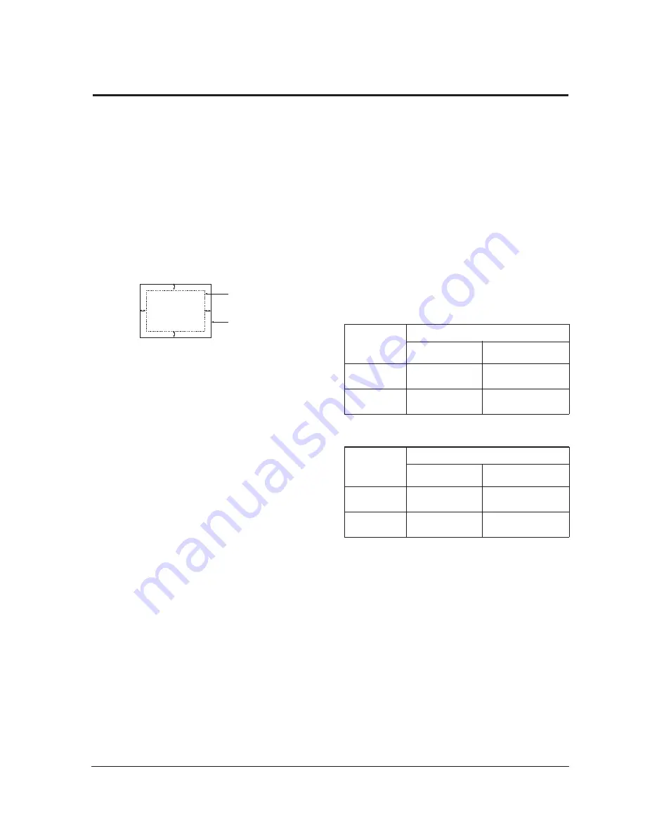
4-2-1 Centering
Centering means to position the center point of
the display in the middle of the display area.
Horizontal size and position and vertical size and
position control the centering of the display.
Adjust the horizontal size and vertical size to their
optimal settings:
355
mm (H) x
266
mm (V)
/920C.
310 mm x 232 mm/720C.
1280
x 1024 mode
(91kHz/85Hz)
Adjust the horizontal position and vertical
position to ² 4.0 mm of the center point of the
screen.
|A-B| ² 4.0 mm. |C-D| ² 4.0 mm.
Figure 4-3. Centering
4-2-1 (a) HORIZONTAL SIZE ADJUSTMENT
CONDITIONS
Scanning frequency:
91 kHz/85 Hz
Display image:
Crosshatch pattern
Brightness:
Cut-off
Contrast:
Maximum
Click on the << or >> box next to
H_SIZE
to
adjust the horizontal size of the display pattern to
355
mm. (Tolerance: ± 3 mm.)
4-2-1 (b) VERTICAL SIZE ADJUSTMENT
CONDITIONS
Scanning frequency:
91 kHz/85 Hz
Display image:
Crosshatch pattern
Brightness:
Cut-off
Contrast:
Maximum
Click on the << or >> box next to
V_SIZE
to
adjust the vertical size of the display pattern to
266
mm. (Tolerance: ± 3 mm.)
4-2-1 (c) HORIZONTAL POSITION ADJUSTMENT
CONDITIONS
Scanning frequency:
91 kHz/85 Hz
Display image:
Crosshatch pattern
Brightness:
Cut-off
Contrast:
Maximum
Click on the << or >> box next to
H_POSI
to
center the horizontal image on the raster.
4-2-1 (d) VERTICAL POSITION ADJUSTMENT
CONDITIONS
Scanning frequency:
91 kHz/85 Hz
Display image:
Crosshatch pattern
Brightness:
Cut-off
Contrast:
Maximum
Click on the << or >> box next to
V_POSI
to
center the vertical image on the raster.
4-2-2 Linearity
Linearity affects the symmetry of images as they
appear on the screen. Unless each row or column
of blocks in a crosshatch pattern is of equal size,
or within the tolerances shown in Tables 4-1 and
4-2, an image appears distorted, elongated or
squashed.
Table 4-1. Factory Preset Modes Linearity
Table 4-2. Other Modes Linearity: VGA, SVGA, XGA,
MAC, etc.
4-2-2 (a) HORIZONTAL LINEARITY ADJUSTMENT
CONDITIONS
Scanning frequency:
91 kHz/85 Hz
Display image:
Crosshatch pattern
Brightness:
Cut-off
Contrast:
Maximum
To adjust the Horizontal Linearity, refer to Tables
4-1 and 4-2 for the tolerance range.
Click on the << or >> box next to
H_LIN
to
optimize the image.
4 Alignment and Adjustments
720C/920C
4-3
4-2 Display Control Adjustments
C
A
DISPLAY AREA
EDGE OF BEZEL
B
D
4 : 3
Horizontal: 20.5~23.5
Vertical :
20.5~23.5
Supported Timing Mode
Each block (14 %)
Difference between
adjacent blocks (5 %)
Horizontal: Less than 1.10 mm
Vertical : Less than 1.10 mm
4 : 3
Horizontal: 20.9~23.1
Vertical : 20.9~23.1
Standard Modes Linearity
Each block (10 %)
Difference between
adjacent blocks (4 %)
Horizontal: Less than 0.88 mm
Vertical : Less than 0.88 mm
Содержание 720C
Страница 33: ...720C 920C 6 1 6 1 720C Exploded View and Parts List ...
Страница 34: ...720C 920C 6 2 6 2 920C Exploded View and Parts Lists ...
Страница 79: ...T601 C639 C609 C636 C638 L601 C604 D637 D608 10 1 Power Parts Schematic Diagram 720C 920C 10 1 ...
Страница 80: ...R299 720C 920C 10 2 10 2 MICOM Parts Schematic Diagram ...
Страница 81: ...720C 920C 10 3 10 3 Horizontal Vertical Processor Parts Schematic Diagram R265 C272 R262 ...
Страница 83: ...R561 R562 R501 C530 L521 R523 R526 720C 920C 10 5 10 5 High Voltage Parts Schematic Diagram ...
Страница 84: ...720C 10 6 1 10 6 1 720C Video Parts Schematic Diagram ...
Страница 86: ...720C 920C 10 7 10 7 Connector and Option Boards Parts Schematic Diagram CN142 slcon4p slcon4p CN141 CN208 ...


