


5 Troubleshooting
720C/920C
5-9
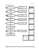
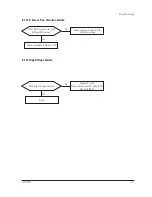
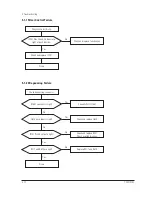
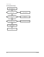
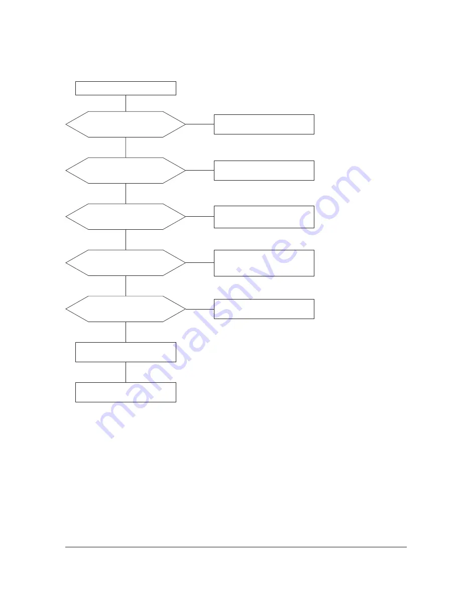
5-1-16 No Video
IC101 Pins 2, 6 and 11 (17”: IC104,
Pin 5, 8, 10) inputs are right?
IC101 Pins 29, 32 and 35
(17”: IC104, Pin 25, 28, 30) outputs
are right?
Check I
2
C bus and +12 V line.
Yes
Yes
No
Check CN101
No
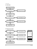
IC102 Pins 4, 6 and 14 (17”: IC105,
Pin 1, 3, 5) outputs are right?
Check +12 V line.
Check and replace IC102 (17”: IC105).
Yes
No
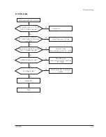
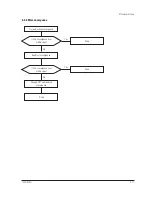
Cathode DC levels are right?
Check +80 V line.
Check and replace IC101 and IC104
(17”: IC104).
Yes
No
G2 voltage is right?
Check G2 wire, CRT Socket board,
and FBT.
Change CRT.
Yes
Done.
No
Check signal cable and connection.
Содержание 720C
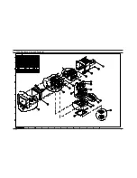
Страница 33: ...720C 920C 6 1 6 1 720C Exploded View and Parts List ...
Страница 34: ...720C 920C 6 2 6 2 920C Exploded View and Parts Lists ...
Страница 79: ...T601 C639 C609 C636 C638 L601 C604 D637 D608 10 1 Power Parts Schematic Diagram 720C 920C 10 1 ...
Страница 80: ...R299 720C 920C 10 2 10 2 MICOM Parts Schematic Diagram ...
Страница 81: ...720C 920C 10 3 10 3 Horizontal Vertical Processor Parts Schematic Diagram R265 C272 R262 ...
Страница 83: ...R561 R562 R501 C530 L521 R523 R526 720C 920C 10 5 10 5 High Voltage Parts Schematic Diagram ...
Страница 84: ...720C 10 6 1 10 6 1 720C Video Parts Schematic Diagram ...
Страница 86: ...720C 920C 10 7 10 7 Connector and Option Boards Parts Schematic Diagram CN142 slcon4p slcon4p CN141 CN208 ...


