5 Troubleshooting
5-8
720C/920C
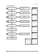
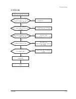
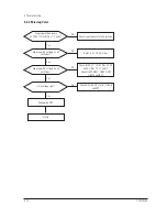
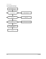
IC101 (17”: IC104, Pin12) Pin 15
input exists and
varies with different patterns?
Check and replace IC101 (17”:IC104).
Input full white pattern to monitor.
No
Yes
T501 Pin 8 output exists?
Check and replace T501.
Yes
No
IC103 (17”: IC04) Pin 16 output
exists and varies with different
patterns?
Check and replace IC103 (17”: IC04).
Yes
No
Check and replace Q101,
Q102 and +12 V line.
Check CN102.
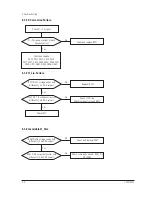
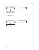
5-1-14 ABL Failure
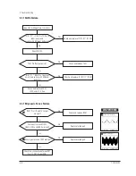
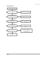
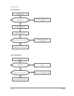
5-1-15 Dynamic Focus Failure
IC261 Pins 18 and 15 output
are right?
Check and replace IC261.
Yes
No
Some parts around Q551,
Q552, Q553 and Q554 are right?
Replace failed part.
Yes
No
Some parts around T502 are right?
Replace failed part.
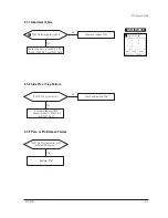
Check the connection between FBT
Pin 13, CRT Socket PCB.
Yes
No
1
0
1
1
1
0
2.20 V (IC251, #15)
CH1 P-P = 2.20 V
CH1 RMS = 2.776 V
1
1
580 V (T551, #1)
CH1 P-P = 580 V
CH1 RMS = 278.2 V
WAVEFORMS
Содержание 720C
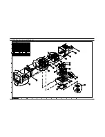
Страница 33: ...720C 920C 6 1 6 1 720C Exploded View and Parts List ...
Страница 34: ...720C 920C 6 2 6 2 920C Exploded View and Parts Lists ...
Страница 79: ...T601 C639 C609 C636 C638 L601 C604 D637 D608 10 1 Power Parts Schematic Diagram 720C 920C 10 1 ...
Страница 80: ...R299 720C 920C 10 2 10 2 MICOM Parts Schematic Diagram ...
Страница 81: ...720C 920C 10 3 10 3 Horizontal Vertical Processor Parts Schematic Diagram R265 C272 R262 ...
Страница 83: ...R561 R562 R501 C530 L521 R523 R526 720C 920C 10 5 10 5 High Voltage Parts Schematic Diagram ...
Страница 84: ...720C 10 6 1 10 6 1 720C Video Parts Schematic Diagram ...
Страница 86: ...720C 920C 10 7 10 7 Connector and Option Boards Parts Schematic Diagram CN142 slcon4p slcon4p CN141 CN208 ...


