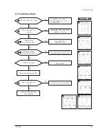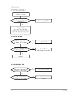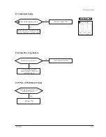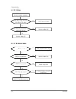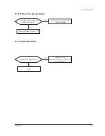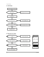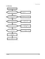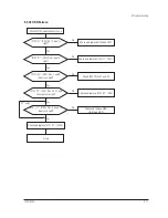
4-3-4 (d) WHITE BALANCE ADJUSTMENT VERIFICATION
Refer to the procedure for 9300K, section 4-3-2 (d).
4-3-5 Luminance Uniformity Check
Luminance is considered uniform only if the ratio
of lowest to highest brightness areas on the screen
is not less than 7.5:10.
CONDITIONS
Scanning frequency:
68 kHz/85 Hz
(1024 x 768)
Display image:
White flat field
Display
size
: 355(H) x 266(V)/920C ~ 310(H) X 232(V)/720C
Brightness:
Cut off point
Contrast:
Maximum
PROCEDURE
Measure luminance at nine points on the display
screen (see figure below).
4-3-6 Focus Adjustment
CONDITIONS
Scanning frequency:
68 kHz/85 Hz
Display image:
ÒHÓ character pattern
Brightness:
Cut off point
Contrast:
Maximum
PROCEDURE
1. Adjust the Focus VR on the FBT to display the
sharpest image possible.
2. Use Locktite to seal the Focus VR in position.
4-3-7 Color Purity Adjustment
Color purity is the absence of undesired color.
Conspicuous mislanding (unexpected color in a
uniform field) within the display area shall not be
visible at a distance of 50 cm from the CRT
surface.
CONDITIONS
Orientation:
Monitor facing east
Scanning frequency:
68 kHz/85 Hz
Display image:
White flat field
Luminance:
Cut off point at the center
of the display area
Note:
Color purity adjustments should only be
attempted by qualified personnel.
PROCEDURE
(adjusting convergence)
For trained and experienced service technicians
only.
Use the following procedure to correct minor
color purity problems:
1. Make sure the display is not affected by
external magnetic fields.
2. Very carefully break the glue seal between the
2-pole purity convergence magnets (PCM), the
band and the spacer.
3. Make sure the spacing between the PCM
assembly and the CRT stem is 29 mm ± 1 mm.
4. Display a green pattern over the entire display
area.
5. Adjust the purity magnet rings on the PCM
assembly to display a pure green pattern.
(Optimum setting: x = 0.295 ± 0.015,
y = 0.594 ± 0.015)
6. Repeat steps 4 and 5 using a red pattern and
then again, using a blue pattern.
Table 4-3. Color Purity Tolerances
(For 9300K color adjustment: x = 0.283 ± 0.02, y = 0
.297
± 0.02)
7. When you have the PCMs properly adjusted,
carefully glue them together to prevent their
movement during shipping.
4 Alignment and Adjustments
720C/920C
4-7
Red:
x = 0.620 ± 0.015
y = 0.334 ± 0.015
Green:
x = 0.289 ± 0.015
y = 0.595 ± 0.015
Blue:
x = 0.153 ± 0.015
y = 0.072 ± 0.015
Figure 4-10 Luminance Uniformity Check Locations
Содержание 720C
Страница 33: ...720C 920C 6 1 6 1 720C Exploded View and Parts List ...
Страница 34: ...720C 920C 6 2 6 2 920C Exploded View and Parts Lists ...
Страница 79: ...T601 C639 C609 C636 C638 L601 C604 D637 D608 10 1 Power Parts Schematic Diagram 720C 920C 10 1 ...
Страница 80: ...R299 720C 920C 10 2 10 2 MICOM Parts Schematic Diagram ...
Страница 81: ...720C 920C 10 3 10 3 Horizontal Vertical Processor Parts Schematic Diagram R265 C272 R262 ...
Страница 83: ...R561 R562 R501 C530 L521 R523 R526 720C 920C 10 5 10 5 High Voltage Parts Schematic Diagram ...
Страница 84: ...720C 10 6 1 10 6 1 720C Video Parts Schematic Diagram ...
Страница 86: ...720C 920C 10 7 10 7 Connector and Option Boards Parts Schematic Diagram CN142 slcon4p slcon4p CN141 CN208 ...


