


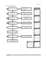
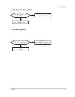

4-3-1 Color Coordinates (Temperature)
Color temperature is a measurement of the
radiant energy transmitted by a color. For
computer monitors, the color temperature refers
to the radiant energy transmitted by white. Color
coordinates are the X and Y coordinates on the
chromaticity diagram of wavelengths for the
visible spectrum.
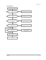
CONDITIONS
Measurement instrument: Color analyzer
Scanning frequency:
68 kHz/85 Hz
Display Size
:
355 (H) x 266 (V)/920C ~ 310 X 232/720C
Display image:
White flat field at
center of display area
Brightness:
Cut-off
Contrast:
Maximum
PROCEDURE
Use the directions in sections 4-3-2 through 4-3-4
to adjust the color coordinates for:
9300K to x = 0.283 ± 0.02, y = 0.29
7
± 0.02
6500K to x = 0.313 ± 0.02, y = 0.329 ± 0.02
5000K to x = 0.346 ± 0.02, y = 0.359 ± 0.02
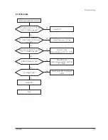
4-3-2 Color Adjustments for 9300K
4-3-2 (a) BACK RASTER COLOR ADJUSTMENT
CONDITIONS
Scanning frequency:
68 kHz/85 Hz
Display image:
Back raster pattern
Brightness:
Cut-off
Contrast:
Maximum
1. Select
COLOR CHANNEL 1
to control the
color for 9300K.
2. Adjust the luminance of the back raster to
between 0.3 to 1ft-L using the
G_CUT
controls.
3. Click on the << or >> box next to
B_CUT
to
set the ÒyÓ coordinate to 0.
297
± 0.02.
4. Click on the << or >> box next to
R_CUT
to
set the ÒxÓ coordinate to 0.283 ± 0.02.
Note:
If the above adjustments cannot be
done to each coordinate, click on the
<< or >> box next to
G_CUT
to decrease
or increase the green cutoff (bias) and
repeat procedures 2 and 3.
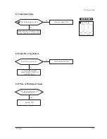
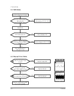
4-3-2 (b) G-GAIN ADJUSTMENT
Figure 4-8. Green Box Pattern
CONDITIONS
Scanning frequency:
68 kHz/85 Hz
Display image:
Green box pattern
Brightness:
Cut-off
Contrast:
Maximum
1. Click on the << or >> box next to
G_GAIN
to
adjust the brightness of the Green Gain to
25 ± 1 ft-L.
Note:
If you canÕt increase the Green Gain to
the appropriate value, click on the >>
box next to increase the
ABL
point.
4-3-2 (c) WHITE BALANCE ADJUSTMENT
CONDITIONS
Scanning frequency:
68 kHz/85 Hz
Display image:
Full white pattern
Brightness:
Cut-off
Contrast:
Maximum
Figure 4-9. Full White Pattern
1. Click on the << or >> boxes next to
R_GAIN
and
B_GAIN
to make the video white.
(For 9300K color adjustment:
x = 0.283 ± 0.02, y = 0.
297
± 0.02.)
Note:
Do not touch the
G_GAIN
controls.
2. Check the ABL. If it is not within the
specifications (30 ± 1 ft-L), use the ABL
controls to adjust it.
3. Select
COLOR FACTORY SAVE
to save the
data.
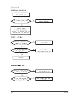
4 Alignment and Adjustments
720C/920C
4-5
4-3 Color Adjustments
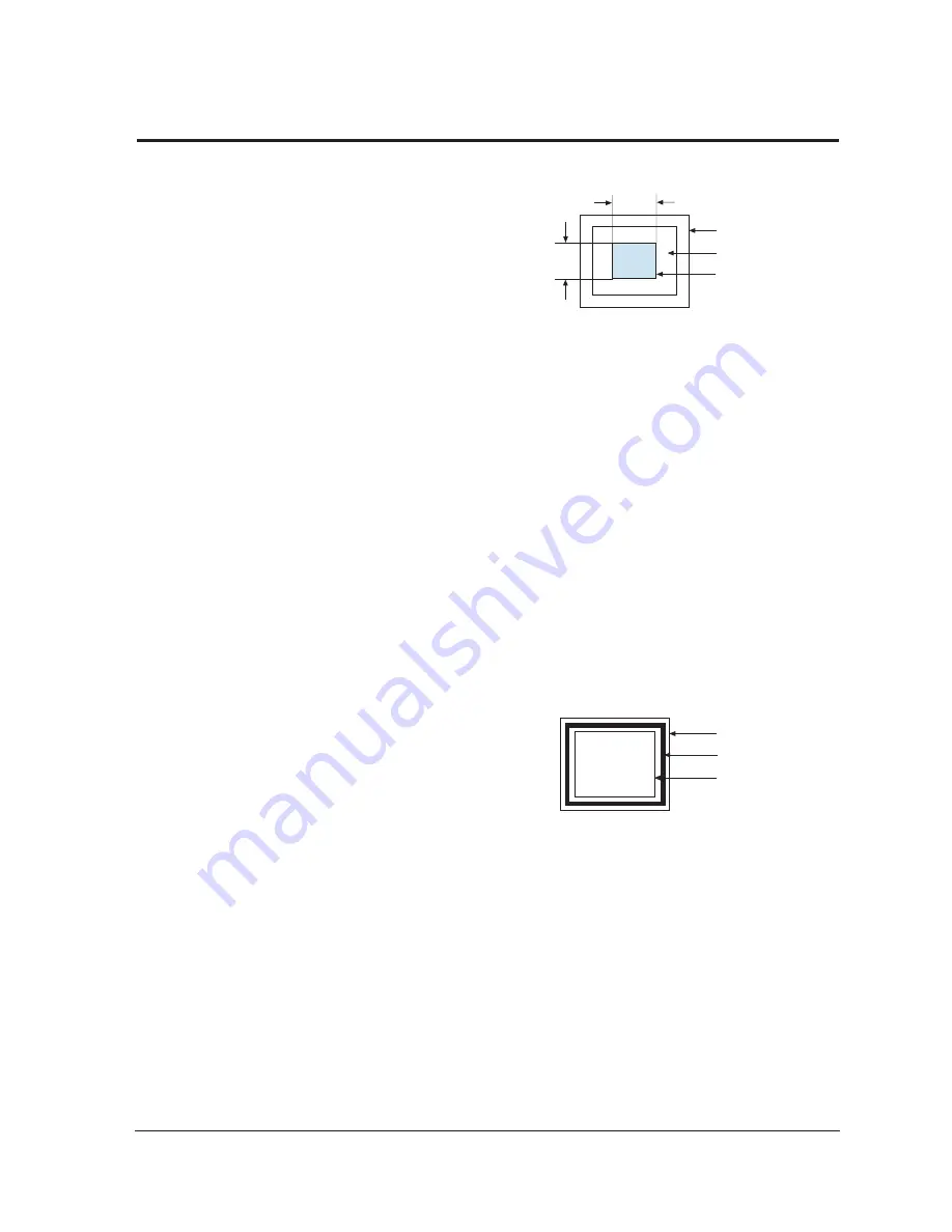
1/3H-1/2H
1/3V-1/2V
FRONT BEZEL OPENING
BACK RASTER
GREEN WINDOW
FRONT BEZEL OPENING
BACK RASTER
WHITE WINDOW
Содержание 720C
Страница 33: ...720C 920C 6 1 6 1 720C Exploded View and Parts List ...
Страница 34: ...720C 920C 6 2 6 2 920C Exploded View and Parts Lists ...
Страница 79: ...T601 C639 C609 C636 C638 L601 C604 D637 D608 10 1 Power Parts Schematic Diagram 720C 920C 10 1 ...
Страница 80: ...R299 720C 920C 10 2 10 2 MICOM Parts Schematic Diagram ...
Страница 81: ...720C 920C 10 3 10 3 Horizontal Vertical Processor Parts Schematic Diagram R265 C272 R262 ...
Страница 83: ...R561 R562 R501 C530 L521 R523 R526 720C 920C 10 5 10 5 High Voltage Parts Schematic Diagram ...
Страница 84: ...720C 10 6 1 10 6 1 720C Video Parts Schematic Diagram ...
Страница 86: ...720C 920C 10 7 10 7 Connector and Option Boards Parts Schematic Diagram CN142 slcon4p slcon4p CN141 CN208 ...


