Chapter 4
Signal Connections
4-6
ni.com
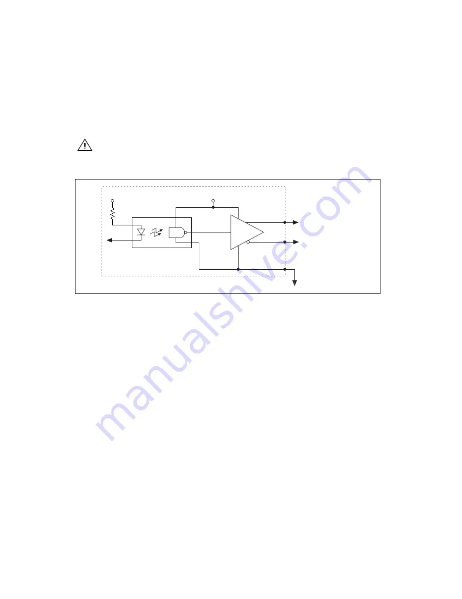
Step and Direction Output Circuit
The Step (CW) and Dir (CCW) outputs are driven by high-speed RS-422
line drivers that feature 20 mA drive capability.
Caution
Do
not
connect these outputs to anything other than a +5 V circuit. The output
buffers will fail if subjected to voltages in excess of +5.5 V.
Figure 4-3.
Step and Direction Output Circuit
Limit and Home Inputs
•
Axis <1..4> Forward Limit Input
•
Axis <1..4> Home Input
•
Axis <1..4> Reverse Limit Input
These inputs are optically isolated sinking or sourcing inputs that are
typically connected to limit switches located at physical ends of travel
and/or at a specific home position. You can use software to enable and
disable limit and home inputs at any time. When enabled, an active limit or
home input causes a full torque halt stop of the associated motor axis.
In addition, an active forward or reverse limit input impedes future
commanded motion in that direction for as long as the signal is active.
By default, limit and home inputs are digitally filtered and must remain
active for at least 1 ms to be recognized. Refer to Appendix A,
, for more information. You can use MAX to disable digital
filtering for limit and home inputs. Active signals should remain active to
prevent motion from proceeding further into the limit. Pulsed limit signals
High Speed Optocoupler
V
cc
AM26C31
RS-422
Line Driver
PCI-7390
Iso +5 V
Isolated Ground
Step– / Dir– Output
Step+ / Dir+ Output


