Chapter 4
Signal Connections
4-10
ni.com
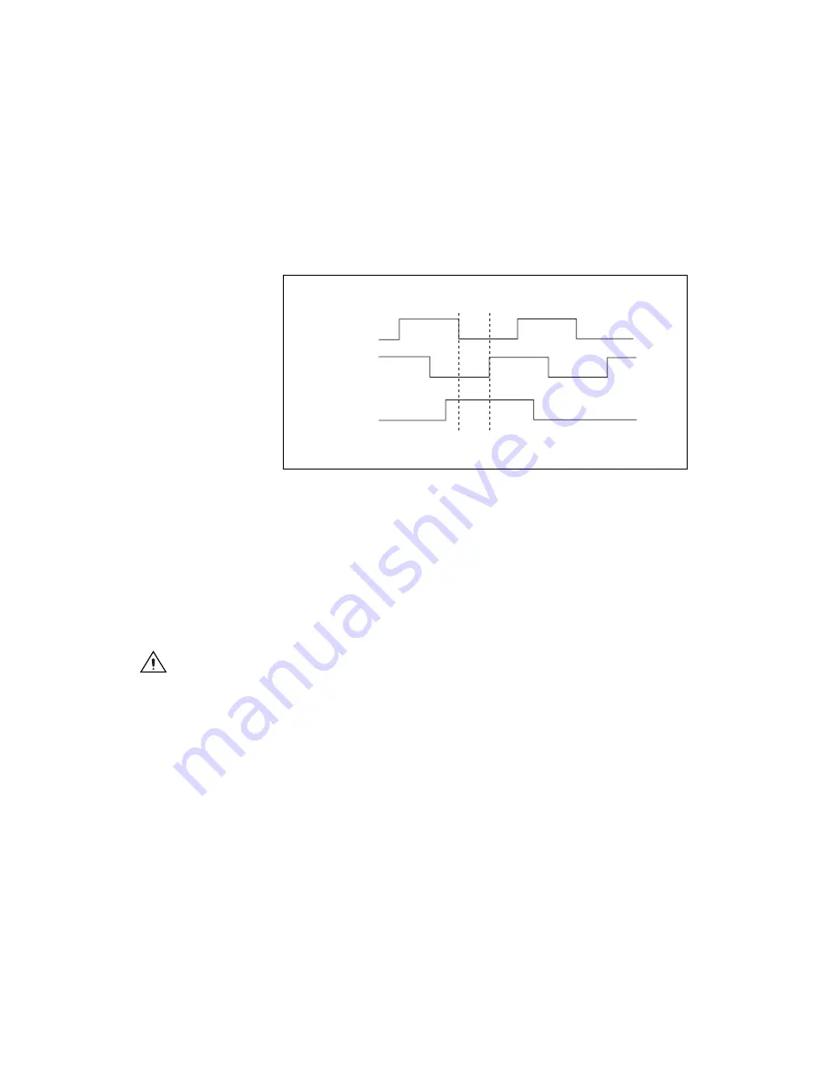
The default MAX settings guarantee that the Find Index routine completes
successfully if the encoder generates a high index pulse when phases A and
B are low and the encoder is connected through an NI MCA or drive
accessory. Figure 4-5 shows the single-ended representation of the
connector signals.
Figure 4-5.
Quadrature Encoder Phasing Diagram
You can set the index reference criteria in MAX to change the pattern of
phases A and B for the index search. You also can set the encoder polarity
for phases A, B, and Z in MAX.
Encoders with differential line driver outputs are strongly recommended
for all applications and must be used if the encoder cable length is longer
than 3.05 m (10 ft). Cables with twisted pairs and an overall shield are
recommended for optimized noise immunity.
Caution
Unshielded cables can cause noise to corrupt the encoder signals, resulting in lost
counts and reduced motion system accuracy.
Phase A
Phase B
Index


