8
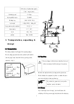
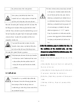
Fig 4-5
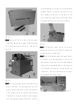
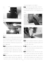
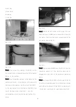
4.2.10 Connect the PU hose described in the step
4.2.7 into the PU hose of the machine cabinet and
insert into the Tee of the air source pipe(Fig4-7)
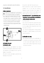
Fig 4-6
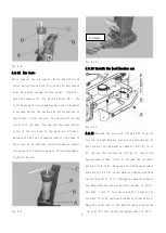
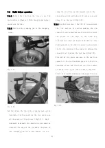
2.11 Mount the horizontal arm protective cover and
detach the cap nut in the front(Fig4-8 A)and the
protective cover fix screw at the back(Fig4-8 B)
and fix screw(Fig4-8 C) on the vertical shaft cap
(Fig4-8 D) and take out the vertical shaft cap.
Fig 4-7
When you detach the vertical shaft cap,
you should support the vertical shaft to prevent
the slide of the vertical to cause the damage to
the machine and injury to the person.
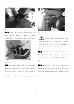
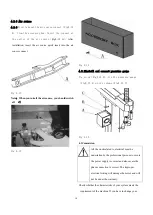
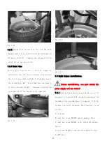
4.2.12 Remove the package of the protective cover.
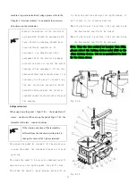
Mount the vertical shaft spring(Fig4-9 D), vertical
shaft cap and fix screw(Fig4-8 D)
、
(Fig4-8 C)and
fix.
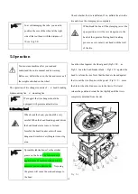
4.2.13 Adjust the set screw at the 2sides of the
column. Release the nuts at the 2sides. Adjust the
screw heads making the gap between them and the side
plane of the column is 0.3mm(Fig4-10). Lock the
nuts.
Содержание TC-1300
Страница 1: ...3456789 C61CN...
Страница 36: ...35...


