7
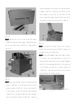
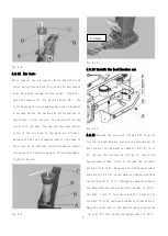
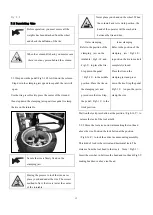
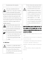
Fig 4-1
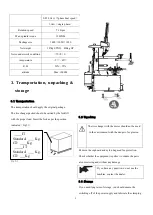
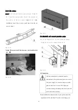
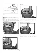
4.2.6 Unscrew off the fix screw on the side panel
(Fig4-2 A)
,Detach the side panel (Fig4-2 B)and the
fix screw on the tool box(Fig4-2 C). Take out the
tool box.
Fig 4-2
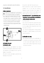
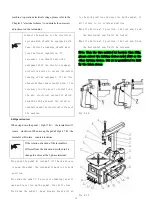
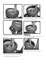
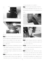
4.2.7 Rise up the column. Insert the PU hose at the
bottom (Fig4-3 A) into the open at the top of the
machine cabinet(Fig4-3 B). Adjust the position
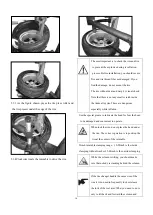
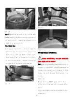
of the column to align the rotation shaft bushing
(Fig4-4 A)to the rotation shaft seat at the upper
seat of the machine cabinet(Fig4-4 B). Take out
the nut and washer at one end of the rotation shaft
assembly(Fig4-1 A)and insert the shaft into the
hole, making the end face of the shaft at the
position 1mm lower than the plane of the seat. Screw
the washer and nut with the torque of 70N·m.
Fig 4-3
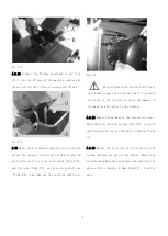
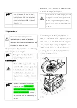
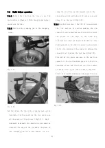
4.2.8 Tilt back the column. Cut up the tie belt
between the retention level (Fig4-5 A)and put out
cylinder piston rod(Fig4-5 B).
4.2.9 Position theΦ16hole under the column(Fig4-6
A ), Detach the retaining washer at one end of
push-out shaft(Fig4-1 B)
,Insert through Φ16hole
and into the corresponding holes of the retention
rod ( Fig4-6E ) and push-out cylinder piston rod
(Fig4-6 D). And out from the hole at the other
end and mount the elastic washer.
Fig 4-4
Содержание TC-1300
Страница 1: ...3456789 C61CN...
Страница 36: ...35...


