24
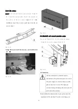
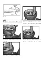
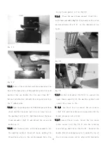
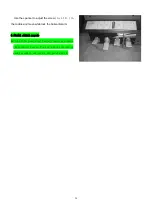
Fig 7-22
7.3.7 Adjust the vertical condition of the helper
column. Release the screw(Fig7-21)according to
the situation of the helper to regulate the set
screw on the helper base making the position of the
column be vertical(Fig7-22). If the column tilts
outward, screw downward the two set adjust screw
outside to make the column be vertical. If the
column tilts inward, screw downward the two set
adjust screw inside to make the column be vertical.
After adjustment, fix and lock the 4pc hex screw.
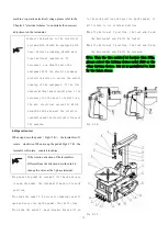
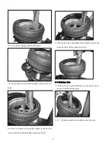
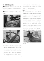
Fig 7-23
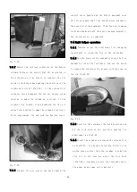
7.3.8 Connect the air source and push upward the
control valve handle and the helper movement seat
will slide upward and if the handle moves downward,
the seat will slide downward. If without air leakage,
crawl and shake and all the parts running normally,
the installation is completed.
7.4 Right helper operation
7.4.1 Prepare as per the universal tire changing
requirement to clamp the tire on the turntable.
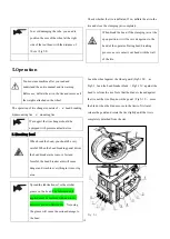
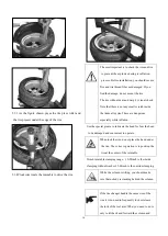
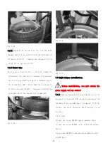
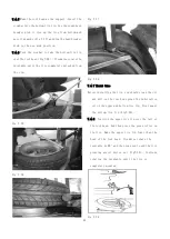
7.4.2 Use the press roller gradually press the tire
meanwhile rotate the turntable,and use the brush
to spread the lubricate the grease or thick soap on
the rim(Fig7-24)
Fig 7-24
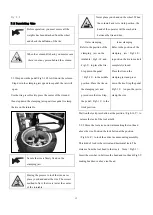
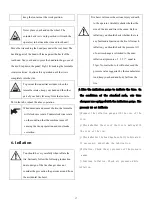
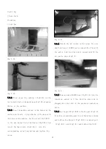
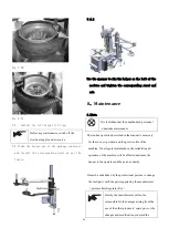
7.4.3 Position the column at the work position and
fix the tool head at the position meeting the
requirement as Fig7-25.
7.4.4 Insert the crowbar in between the rim and tire
as Fig7-25). Use handle valve(Fig 7-24)to rise
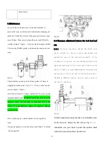
up the press roller. Turn the crowbar to take the
tire lip to the position above the tool head
(Fig7-26)
,Clockwise rotate the turntable until
the upper bead comes out completely.
Содержание TC-1300
Страница 1: ...3456789 C61CN...
Страница 36: ...35...

