3 UPS Functional Descriptions
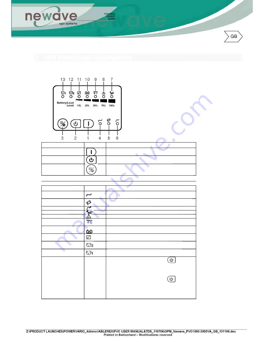
3.1 UPS Front Panel Display Descriptions
Control Keypads
Symbols Functional Descriptions
1. ON
UPS Power-On Switch
2. OFF
UPS Power-Off Switch
3.Self-Test(Alarm Silence)
a. Command the UPS to perform self-testing
b. Alarm Silence -
To mute the alarm buzzer (Do not press & hold for > 1 sec)
LED Indicators
Symbols Functional Descriptions
4. Normal Mode LED
LED illuminated indicates utility voltage within tolerance
(120Vac~280Vac)
5. Battery Mode LED
LED illuminated indicates utility outage or out of tolerance,
loads supply by battery power
6. Bypass Mode LED
LED illuminated indicates bypass supply is normal
7. Overload LED
Red LED illuminated indicates UPS is overloaded
8. Fault LED
Red LED illuminated indicates fault or abnormal conditions
9. Site wiring fault LED
Red LED illuminated indicates Live & Neutral lines are
connected wrongly or High Neutral-Ground voltage
10.Battery Bad/Weak LED
Red LED illuminated indicates low battery power or faulty
battery bank
11.Self Test LED
Green LED illuminated indicates successful self-test and no
abnormal conditions or faults were found
12.Outlet2 LED
Green LED illuminated indicates UPS Outlets 2 are
enabled and ready to supply loads
13.Outlet1 LED
Green LED illuminated indicates UPS Outlets 1 are
enabled and ready to supply loads
7 11 LEDs (% Indicating
Bars)
a. During Normal Mode : Press and hold for 1 sec,
the 7~11 LEDs will function as Load Rate indicators
showing 100%, 75%, 50%, 25% or 10% of UPS capacity
used. These LEDs will stop illuminating after 10 sec.
b. During Battery Mode : Press and hold for 1
sec > the 7~11 LEDs will function as Battery Power
indicators showing 100%, 75%, 50%, 25% or 10% Battery
Power remaining. These LEDs will stop illuminating after 10
sec.
Содержание 1000-3000VA
Страница 2: ...Intelligent True On Line Uninterruptible Power Supply UPS For Corporate IT User Installation Guide...
Страница 13: ...4 3 Tower Configuration Setup Step 1 Step 2...
Страница 14: ...Step 3 Step 4...
Страница 15: ...4 4 Rack Mount Configuration Setup Step 3 Step 4 Step 5...
Страница 16: ...Step 6 Step 7...
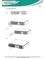
Страница 19: ...4 5 6 Battery Replacement Step 1 Step 2 Step 3...
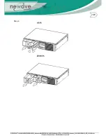
Страница 20: ...Step 4...
Страница 38: ...10 3 3 Installation Instructions Tower installation Stand alone unit Step 1 Step 2...
Страница 39: ...Use with UPS Step 1 Step 2...
Страница 40: ...10 3 4 Rack Mount installation Step 1 Step 2...
Страница 41: ...Step 3 Step 4...
Страница 42: ...Second Battery First Battery Bank UPS Connect DC Cable...
Страница 44: ...Step 3 Step 4 10 3 7 Specifications...
Страница 46: ...11 Technical Specifications...


