


Internal Cabling Diagrams 10-5
Connecting with Disk Expansion Unit
A disk expansion unit is an exclusive device that can install up to 14 hard disk drives. (The number
of hard disk drives depends on the model.) The server containing a Disk Array Controller (N8103-
90) can connect one or two of these devices. For details on the number of devices connected, see the
manuals provided with the Disk Array Controller and disk expansion unit.
IMPORTANT:
A disk expansion unit is provided with no hard disk
drives. You need to purchase hard disk drives separately.
An optional cable may be required to connect with a disk expansion unit. Refer to the manual
coming with the disk expansion unit for details.
After connecting the disk expansion unit, use WebBIOS or Universal RAID Utility to set the disk
expansion unit in a RAID System (RAID0, RAID1, or RAID5). For details on settings and the
setting methods, refer to the manual provided with the board.
While a disk expansion unit is set in a RAID System, you can use the "Auto Rebuild" feature of the
N8103-90 Disk Array Controller to restore data if one of the hard disk drives installed in the disk
expansion unit fails. (Replace the failing hard disk drive while the power is on. (Hot swapping))
IMPORTANT:
When the Disk Array Controller (N8103-90) is
installed, do not let the system enter hibernation or standby mode.
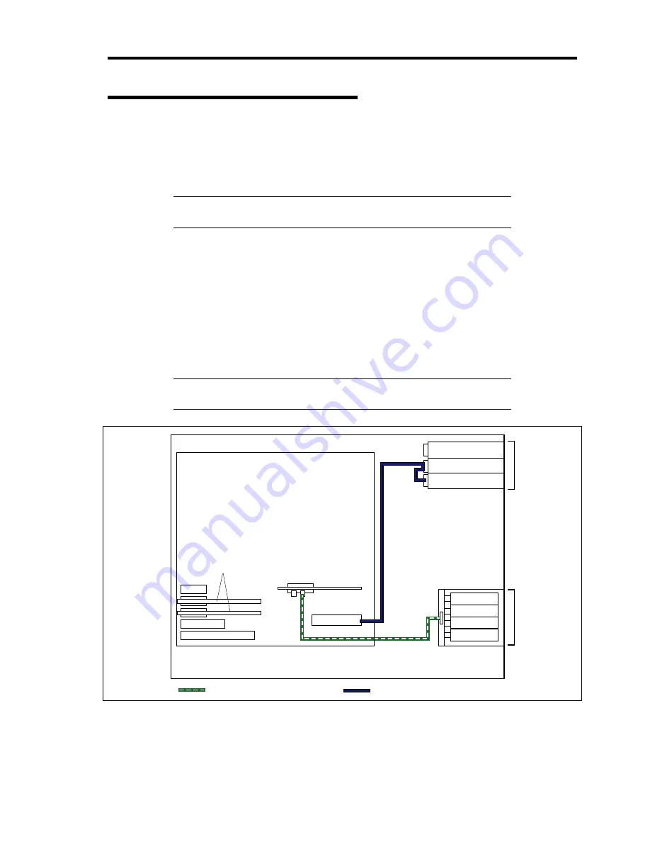
(IDE device)
Optical disk drive
5.25-inch
device bay
3.5-inch hard
disk drive bay
Hard disk drives
are optional.
Mother board
SAS cable
IDE cable
PCIe #5
PCIe #4
PCI-e #3
PCI #2
PCI-X #1
PCIe #6
IDE
ID3
ID2
ID1
ID0
Internal RAID
controller
N8103-90
Disk Array Controller
Содержание Express5800/120Lj
Страница 16: ...x This page is intentionally left blank ...
Страница 36: ...2 8 General Description Rear View 1 2 3 4 5 6 7 8 9 10 11 12 13 1 14 12 14 12 14 13 3 13 2 15 ...
Страница 108: ...4 40 Configuring Your Server The detailed settings is continued to the next page Click Next to view more information ...
Страница 119: ...Configuring Your Server 4 51 Use this menu to define several physical drives PD as a disk group DG ...
Страница 143: ...Configuring Your Server 4 75 3 Setting menu for VD 0 is displayed ...
Страница 195: ...Installing and Using Utilities 6 9 4 Click Parameter File Creator Parameter File Creator will appear ...
Страница 220: ...7 12 Maintenance This page is intentionally left blank ...
Страница 300: ...9 42 Upgrading Your Server Removal Remove the HDD cage in the reverse procedure of the installation ...
Страница 316: ...9 58 Upgrading Your Server Removal Remove the 5 25 inch device in the reverse procedure of the installation ...
Страница 352: ...9 94 Upgrading Your Server This page is intentionally left blank ...
Страница 353: ...Chapter 10 Internal Cabling Diagrams Internal cable connections of the server are shown below ...
Страница 360: ...10 8 Internal Cabling Diagrams This page is intentionally left blank ...
Страница 362: ...A 2 Specifications This page is intentionally left blank ...
Страница 370: ...C 2 IRQ This page is intentionally left blank ...
Страница 426: ...F 2 Using a Client Computer Which Has a CD Drive This page is intentionally left blank ...
Страница 430: ...G 4 Product Configuration Record Table This page is intentionally left blank ...


