background image

3. Names and Functions of Parts


Scalable Modular Server DX2000    User’s Guide 

27


Chapter1  General Description 

3.4 


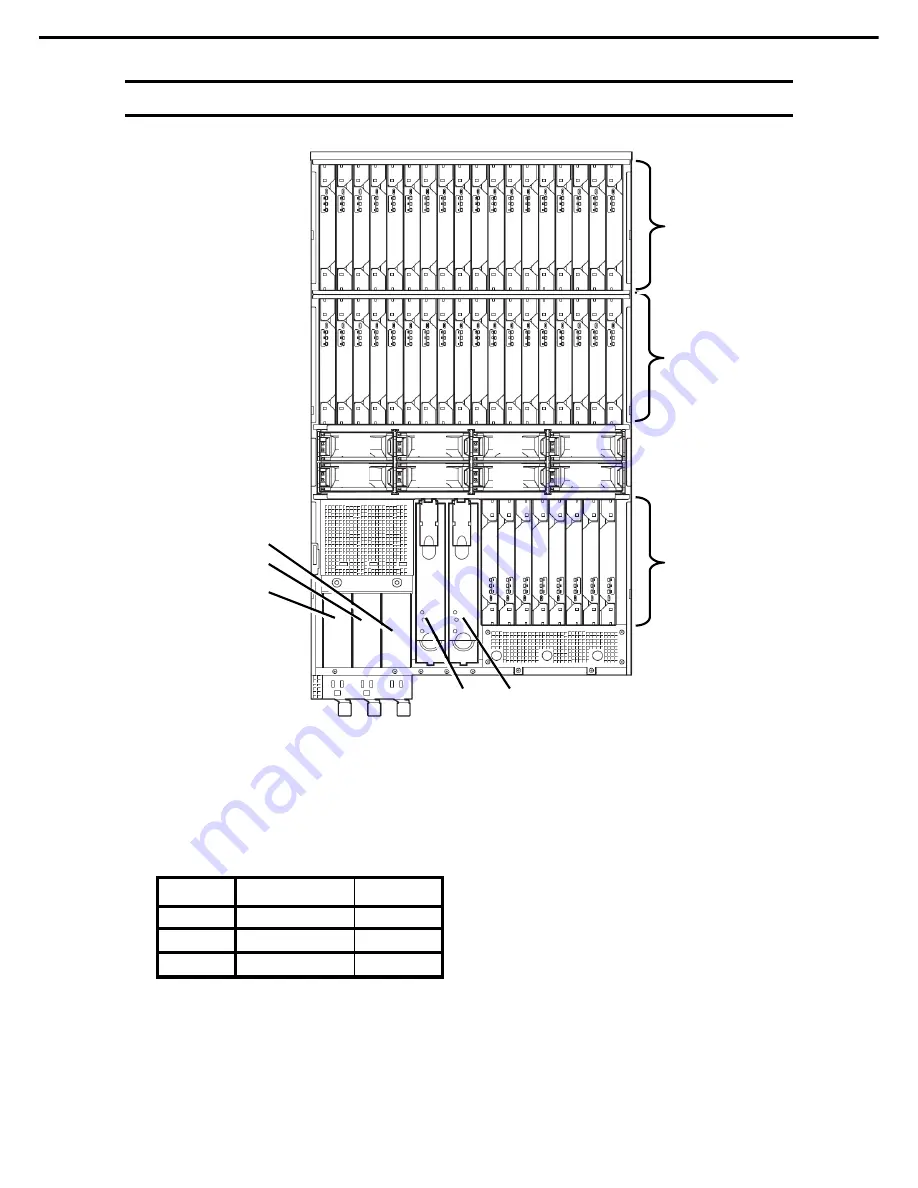
Internal View 


(1) Module 

slot 


The sequential number added to each number in 

parentheses indicates the slot row number.   

The modules that can be installed in each slot are shown in 

the table below.   

Slot ID is indicated at the vicinity of the slot by the number. 


* The number of installable modules varies depending on 

modules implemented. 

 
(2)  NW switch modules 
   

    -1    NW switch 1 

        -2    NW switch 2


(3) Cooling 

fans 

-1 FAN1 
-2 FAN2 
-3 FAN3 
-4 FAN4 
-5 FAN5 
-6 FAN6 
-7 FAN7 
-8 FAN8 


(4)  Power supply unit 

        -1    POWER1 
        -2    POWER2 
        -3    POWER3


(1)-1


From the right side ID =01 to 18 

(4)-1 

(2)-1 

(2)-2 

(1)-3


From the right side ID=37 to 44 

(4)-2 

(3)-1 

(1)-2


From the right side ID=19 to 36 

(4)-3 

(3)-2 

(3)-3 

(3)-4 

(3)-5 

(3)-6 

(3)-7 

(3)-8 


Max. number of 

installable modules 

Slot ID 

1st row 

18 

01 to 18 

2nd row 

18 

19 to 36 

3rd row 

37 to 44 

Содержание DX2000

Страница 1: ...Server DX2000 Chapter 1 General Description Chapter 2 Installation and Connection Chapter 3 Setup Chapter 4 NW Switch Module Chapter 5 Replacing Modules Chapter 6 Appendix February 2016 NEC Corporati...

Страница 2: ...isk Chapter 4 NW Switch Module Features supported by internal switch module how to setup switches and initial settings for network Chapter 5 Replacing Modules How to replace internal modules Chapter 6...

Страница 3: ...2 Standard Features 19 2 1 Management Features 21 CSC modules 21 2 1 1 Server modules 22 2 1 2 3 Names and Functions of Parts 23 3 1 External View 23 3 2 Front view 24 3 3 Rear View 26 3 4 Internal Vi...

Страница 4: ...s and Key Usage 74 6 4 Cases that require configuration 76 7 Installing OS 77 8 Turning Off the Server 78 9 DX2000 Utility Disk 79 9 1 Features of DX2000 Utility Disk 79 Chapter 4 NW Switch Modules 80...

Страница 5: ...Contents Scalable Modular Server DX2000 User s Guide 5 2 Block Diagram of This Server 103 3 Installing the Server on a Non NEC Rack 104 3 1 Requirements 104 4 Revision Record 106...

Страница 6: ...ndicates the presence of a hazard if the instruction is ignored An image in the symbol illustrates the hazard type Prohibited Action This symbol indicates prohibited actions An image in the symbol ill...

Страница 7: ...ons could occur Note Indicates items that must be confirmed when handling the server or operating software Tips Indicates information that is helpful to keep in mind when using this server Hard disk d...

Страница 8: ...of the United States Adobe the Adobe logo and Acrobat are trademarks of Adobe Systems Incorporated PCI Express is a trademark of Peripheral Component Interconnect Special Interest Group All other prod...

Страница 9: ...specific prior written permission THIS SOFTWARE IS PROVIDED BY THE COPYRIGHT HOLDERS AND CONTRIBUTORS AS IS AND ANY EXPRESS OR IMPLIED WARRANTIES INCLUDING BUT NOT LIMITED TO THE IMPLIED WARRANTIES OF...

Страница 10: ...AND ANY EXPRESSED OR IMPLIED WARRANTIES INCLUDING BUT NOT LIMITED TO THE IMPLIED WARRANTIES OF MERCHANTABILITY AND FITNESS FOR A PARTICULAR PURPOSE ARE DISCLAIMED IN NO EVENT SHALL THE OpenSSL PROJEC...

Страница 11: ...OT LIMITED TO THE IMPLIED WARRANTIES OF MERCHANTABILITY AND FITNESS FOR A PARTICULAR PURPOSE ARE DISCLAIMED IN NO EVENT SHALL THE COPYRIGHT OWNER OR CONTRIBUTORS BE LIABLE FOR ANY DIRECT INDIRECT INCI...

Страница 12: ...hemeris ipmitool 1 5 4 http sourceforge net projects ipmitool BSD License http sourceforge net projects ipmitool MD5 N A http opensource apple com source network_cmds network_cmds 328 ping6 tproj md5...

Страница 13: ...ent without permission from NEC Corporation 4 Every effort has been made to ensure the completeness of this document However if you have any concerns or discover errors or omissions please contact you...

Страница 14: ...Warning labels Warning label are attached on or near the components with potential hazards This label is either attached or printed on the component to draw attention from users to potential hazards i...

Страница 15: ...r transportation After storage After the server is used following a period of disuse in which storage conditions did not conform to those that guarantee server operations temperature 10 to 40 C humidi...

Страница 16: ...screen from reflecting bright lights and to make the display contents easy to see Working without adjusting the display to a comfortable angle makes it difficult for you to maintain a proper posture...

Страница 17: ...cription This chapter introduces the features of this server and the name of each part 1 Introduction 2 Standard Features This section describes the server s features and the server management 3 Names...

Страница 18: ...n processor NEC s latest technology and architectures realize high power and high speed operation that cannot be matched by existing servers The server is designed with consideration of not only the d...

Страница 19: ...r server module High speed memory access DDR4 21330 supported Dual channel Two 10G Base KR compliant LAN ports on server module Can keep two 40 Gbps interfaces per network switch module Internal L2 SW...

Страница 20: ...hassis Expandability Up to 44 Server modules can be installed in a 3U chassis Flexible combination of server modules 10G LAN module SAS RAID controller meet user s needs 16 ports for standard LAN and...

Страница 21: ...oards 1 and chassis System Information about items such as UID LED and time 1 Power supply Control the power supplied to all server modules in the chassis in a batch and check their status SEL System...

Страница 22: ...ss MAC address and firmware version Information of field replaceable unit FRU information Information about boards System Information about items such as UID LED and time Power supply Control the powe...

Страница 23: ...ns of Parts Scalable Modular Server DX2000 User s Guide 23 Chapter1 General Description 3 Names and Functions of Parts This section describes the names of the server parts 3 1 External View Top cover...

Страница 24: ...ion with the BMC is still possible 4 Micro USB connector for connecting management PC Serially connected with each BMC of server modules NW switch modules and CSC nodules implemented on this server Co...

Страница 25: ...to identify a specific server among multiple servers installed in a rack Especially when performing maintenance from behind the server lighting the LED will help you to identify which server to work w...

Страница 26: ...t Basic unit PCI 1 Power unit Power supply to the main unit 2 AC inlet Socket to connect the power cord 3 CSC modules Modules to monitor sensors of the main unit 4 NW switch modules 4 1 NW switch modu...

Страница 27: ...cinity of the slot by the number The number of installable modules varies depending on modules implemented 2 NW switch modules 1 NW switch 1 2 NW switch 2 3 Cooling fans 1 FAN1 2 FAN2 3 FAN3 4 FAN4 5...

Страница 28: ...of module in the third row Slot ID Server 1 Server module ID 01 Server 2 Server module ID 02 Server 3 Server module ID 03 Server 18 Server module ID 18 Second row Unit of Server Name of module in the...

Страница 29: ...0G LAN module ID 06 Server 9 Server module ID 17 10G LAN module ID 18 First row Unit of Server Name of module in third row Slot ID Server 10 Server module ID 19 10G LAN module ID 37 Server 11 Server m...

Страница 30: ...ts Unit of Server Name of module in first row Slot ID Server 1 Server module ID 01 Server 2 Server module ID 02 Server 3 Server module ID 03 Server 18 Server module ID 18 First row Second Third row Un...

Страница 31: ...The switch to turn on off the UID lamp Press the switch once to turn on the UID lamp Press it again to turn it off The UID lamp is lit by a command from the software 2 BMC RESET Switch The switch to r...

Страница 32: ...The following table describes each STATUS LED status and its meaning STATUS LED status Description Off The power is off The system is normally running On amber A CPU error has occurred Abnormal CPU t...

Страница 33: ...off STATUS LED 2 The STATUS LED lighting in amber indicates any trouble in the hardware The status of the STATUS LED and the meaning are as follows STATUS LED status Description Off The power is off T...

Страница 34: ...l number added to each number in parentheses indicates the port number 2 QSFP module slot LINK ACT LED LINK ACT LED ofeach QSFP module slot LED to indicate the access status of LAN 3 LAN connector ded...

Страница 35: ...ected with a network normally Flashing green The server is accessing a network Off The server is disconnected from a network SPEED LED M These LEDs indicate with which interface protocol the managemen...

Страница 36: ...ule is turned off STATUS LED 2 The LED lighting in amber indicates any trouble in the server The status of the STATUS LED and the meaning are as follows Status of STATUS LED Description Light off The...

Страница 37: ...e software It lights up in tandem with the UID LED of the server module lighted remotely The status of the UID LED and the meaning are as follows Status of UID LED Description Lighting in blue When th...

Страница 38: ...amber The power cable is not connected to the power supply unit due to redundant power configuration Connect the power cable Flashing amber The power unit is faulty Replace the failed power supply uni...

Страница 39: ...Light off The power is not supplied Lighting in green The power is supplied STATUS LED 2 While the fan is running normally the STATUS LED is off If the fan fails the STATUS LED lights amber The follow...

Страница 40: ...on and connection This chapter describes preparations and connection for using this server 1 Installation This section describes how to select an installation site appropriate to the server 2 Preparat...

Страница 41: ...Precautions for Use Use only in the specified environment Do not connect the ground wire to a gas pipe CAUTION Be sure to observe the following precautions to use the server safely Failure to observe...

Страница 42: ...Place where the air or dust includes components accelerating corrosion ex sulfur sodium chloride or conductive metals Place where chemicals may be accidentally sprayed over Place where a carpet not su...

Страница 43: ...drawing devices mounted on the top of the rack Secure at least 400mm from the top of the rack to the ceiling When you mount a device on the rack to maintain it from the top of the equipment you need...

Страница 44: ...rns injury and property damage For details refer to Safety precautions in Precautions for Use Do not drop Do not leave the server being pulled out Do not install with the cover removed Do not get your...

Страница 45: ...1 side in the server chassis and slide the inner rail toward rear of the server Make sure the lock at around the center of inner rail clicks to indicate that the rail is locked Install another inner...

Страница 46: ...mewhat unsteady it is not defective Attach the R and L slide rails 4 Installing the server CAUTION Be sure to observe the following precautions to use the server safely Failure to observe the precauti...

Страница 47: ...r with three or more persons 1 Pull out the middle rail of the right and left slide rails until it is locked up 2 Three or more workers should firmly hold the server and install it on the rack 3 Push...

Страница 48: ...rver DX2000 User s Guide 48 Chapter 2 Installation and connection 5 Push the server until the right and left rails on the front side are locked 6 Mount the cable fixing metal fitting 7 Installing the...

Страница 49: ...r Connect the AC cable LAN cable and optical cable and fix them to the cable fixing bracket with cable band attached to the slide rail Then connect the SAS cable Secure enough bending radius of the op...

Страница 50: ...n 2 Make ready to install the cable arm Before installing the cable check that the direction of the section C is that shown in the lower left figure If you find it reverse change the direction by pres...

Страница 51: ...Installation and connection 3 Insert sections A and B into the slide cable side and push them until they get locked 4 Sections A and B have been installed 5 Insert the section C into the slide rail s...

Страница 52: ...AS cable with cable bands by lifting them to secure bending radius as shown in the figure After routing cables close the lids of all baskets as shown in the figure 8 Draw the server slowly and make su...

Страница 53: ...th three or more persons Make sure that the DC power of the server is off and then disconnect the power cords and all interface cables from the server Three power cords are connected to the server Be...

Страница 54: ...tool contact your sales representative WARNING Be sure to observe the following precautions to use the server safety Failure to observe the precautions may cause death or serious injury For details re...

Страница 55: ...55 Chapter 2 Installation and connection Front Image of connecting devices Rear view 8 a 5 3 6 7 9 10 11 12 8 b 15 4 SMNP Manager Server for OS install DHCP Server TFTP Server DHCP Server TFTP Server...

Страница 56: ...dvance to allocate an IP address of DX2000 from the DHCP server 6 Server for OS install Use to install OS to each server module 7 Hub or switching Hub for data Used to relay the connection between the...

Страница 57: ...o CSC Modules This section describes how to connect to CSC Modules 4 Connection to BMC This section describes how to set BMC firmware 5 Turning on DC of Server Modules This section describes how to se...

Страница 58: ...power plugs on the rear of the server Turn on the DC power to server modules by using the following procedure Tips When turning on and off the server by inserting and removing AC cables wait at least...

Страница 59: ...til initialization is completed Wait for a moment until the status LED stops lighting in amber it takes about 50 seconds as a rough indication At that time check the Power LED on the power supply unit...

Страница 60: ...utility under util folder in the attached DC2000 Utility Disk to a server management terminal 64bit version Linux Grant an appropriate owner authority to the copied server management utility so that...

Страница 61: ...80 AB 02 A8 192 168 0 02 LAN SW2 94 DE 80 AB 02 A9 192 168 0 03 CPU Board1 94 DE 80 AB 00 34 192 168 0 11 94 DE 80 AB 03 D2 94 DE 80 AB 03 D3 CPU Board2 94 DE 80 AB 00 35 192 168 0 12 94 DE 80 AB 03...

Страница 62: ...80 AB 02 A9 192 168 0 03 CPU Board1 94 DE 80 AB 00 34 192 168 0 11 94 DE 80 AB 03 D2 94 DE 80 AB 03 D3 CPU Board2 94 DE 80 AB 00 35 192 168 0 12 94 DE 80 AB 03 D4 94 DE 80 AB 03 D5 CPU Board3 94 DE 8...

Страница 63: ...he same network as the IP address of CSC modules obtained in section 2 3 See EXPRESSSCOPR Engine 3 User s Guide for the detail http CSC_HostPort or https CSC_HostPort Example http 192 168 1 1 80 The d...

Страница 64: ...ng CSC module FW When you logged in the management screen of the CSC modules configure various settings as required Open the Setting tab to set the following items Network Property Set the following i...

Страница 65: ...ser name Enter up to 15 characters for a login user name Password Enter up to 19 characters for a password Confirmation password Enter the same character string as the password Privilege Set the autho...

Страница 66: ...ds Default is 30 seconds To 1 Set this when you enable Alert Required To 2 Set this when you enable Alert To 3 Set this when you enable Alert From Set this when you enable Alert Reply to Set this when...

Страница 67: ...e function Alert Enable Disable Default Chassis name Set this when you enable Alert Required Community name Set this when you enable Alert Required Message Process Set this when you enable Alert Alert...

Страница 68: ...logging SEL Default Clear all SEL Overwrite old SEL HTTP Enable Disable Default HTTPS Enable Disable Default Operation Enable Disable Default Platform Event Filtering Enable Disable Default ESMPRO Man...

Страница 69: ...om a management terminal on the same network as the IP address of BMC of each slot obtained in section 2 3 http BMC_HostPort or https BMC_HostPort Example http 192 168 1 1 80 The default login user na...

Страница 70: ...diagnostic management tools and utilities to control the device en bloc Do not delete this account When you change this password set the same password in the device to be controlled 4 2 Setting BMC Wh...

Страница 71: ...SOL to display and operate the POST screen and the BIOS SETUP Utility screen To enable this feature specify the settings below Operation on the management terminal Start the terminal emulator and spec...

Страница 72: ...This section describes how to turn on DC for any CPU module For a Web browser Turn on DC from the Web console screen of BMC of the slot for which DC is turned on For IPMI Turn on DC by sending an IPM...

Страница 73: ...ver module by referring to Chapter 3 1 Turning on the Server After a while the following message will be displayed on the lower left of the screen The message varies depending on the environment Press...

Страница 74: ...arameter of the selected item You cannot use this key when a menu which has on the left is selected Enter key Press this key to confirm the selected parameter Esc key Pressing this key takes you to th...

Страница 75: ...ters are restored Load Previous Values Yes No F3 key If you press this key the following window appears If you select Yes the parameters of the currently selected item are restored to their default se...

Страница 76: ...Basic Change date and time Main System Date Main System Time Configurable on OS Enable NumLock when the power is turned on Set Boot Bootup Numlock State to On Boot Set the boot mode to the UEFI mode...

Страница 77: ...7 Installing OS Scalable Modular Server DX2000 User s Guide 77 Chatpter 3 Setup 7 Installing OS Install OS on the intended server module See the installation guide of each OS for installing OS...

Страница 78: ...ch server module enters the DC OFF state 3 To completely turn off the AC power to this server disconnect the AC cable connected on the rear of the server and confirm that the POWER switch and POWER LE...

Страница 79: ...refer to Chapter 1 6 System Diagnostic Tool and 7 Server Management Utility in DX2000 Maintenance Guide System diagnosis function Diagnoses your server system Driver Stores the following driver that i...

Страница 80: ...res of NW switch modules in this server setup and initial values of networks 1 Outline of NW Switch Modules This section describes the support function list of NW switch modules 2 Accessing NW Switch...

Страница 81: ...1 Two NW switch modules are mounted per basic equipment Two NW switch modules are connected to each server modules in 10Gbps inside the server In the configuration with 10G LAN modules each NW module...

Страница 82: ...switch modules from a management terminal on the same network as the IP address of each NW switch module obtained in section 2 3 Access by telnet or ssh is supported scheduled See Document of NW swit...

Страница 83: ...uide 83 Chapter 4 NW Switch Modules 3 Setting NW Switch Modules Set NW switch modules See Document of NW switch modules for the detail NEC Scalable Modular Server DX2000 NW Switch Configuration Guide...

Страница 84: ...X2000 User s Guide 84 NEC Scalable Modular Server DX2000 Replacing Modules This chapter describes procedures to replace modules in the server 1 Replacing Internal Modules Describes about replacement p...

Страница 85: ...replacing modules properly and safely WARNING Be sure to observe the following precautions to use the server safety Failure to observe the precautions may cause death or serious injury For details re...

Страница 86: ...ratures Do not get your fingers caught when installing components 1 If the server is mounted on a rack use the UID switch to identify the target server Refer to Chapter 5 1 3 Identifying the Server by...

Страница 87: ...ting a cable from the server when the server is running Press the UID switch to turn the UID LED on Each time the UID switch is pressed turning on and off the LED is toggled Click the UID button red c...

Страница 88: ...one of the power supply units fails Replacing a faulty power supply unit 1 4 1 Replace the power supply unit only when it is faulty CAUTION Be sure to observe the following precautions to use the ser...

Страница 89: ...r of each power supply 1 unit The LED of the faulty power supply unit lights amber or flashes amber Disconnect the AC power cord from the faulty power supply unit 2 Press the lever of the power supply...

Страница 90: ...top cover before replacing a module installed in this server the following component 1 Refer to steps 1 and 2 in Chapter 5 1 2 Overview of Replacing Modules for preparations 2 Loosen the screw on the...

Страница 91: ...by NEC Replacement 1 6 1 Follow the steps below to replace the server module 1 Refer to steps 1 to 3 in Chapter 5 1 2 Overview of Replacing Modules for preparations 2 Locate the server module you are...

Страница 92: ...G LAN module After replacing the 10G LAN module start the server module and check if the 10G LAN module is correctly recognized Important Backup the configuration of NW switch modules as required See...

Страница 93: ...and pull it straight up Important When you pull out modules be sure to remove by orange ejector 4 Insert the new server module or 10G LAN module into the slot guide slowly and carefully Important Mak...

Страница 94: ...at the server module is installed vertically on the base board Note If the module is not level remove it and then install it again The following probably causes the server module not to be level The s...

Страница 95: ...ons for anti static measures in this document to take measures against anti static before performing an operation Do not use unauthorized modules Replacement 1 7 1 Follow the steps below to replace a...

Страница 96: ...Hold the ejector and the handle firmly and pull out the switch module slowly 6 Install it slowly to the guide of the slot on which the replacement NE switch module is mounted 7 Lay stress on the hand...

Страница 97: ...rver DX2000 User s Guide 97 Chapter 5 Replacing Modules 1 8 CSC Modules Replacement 1 8 1 1 Turn the hand screw fixing the CSC module to pull it out slowly 2 Install the replacement CSC module firmly...

Страница 98: ...to Handling precautions for anti static measures Use only a fan module authorized by NEC Replacement 1 9 1 Follow the steps below to replace a fan module 1 Refer to steps 1 to 3 in Chapter 5 1 2 Over...

Страница 99: ...becomes slow and then pull out the fan module completely Touching the rotating fan blade may cause an injury Do not touch the fan blade that is rotating 6 Install the new fan module in the reverse ord...

Страница 100: ...ations This section shows specifications of this server 2 Block Diagram of This Server This section shows the block diagram of this server 3 Installing the Server on a Non NEC Rack This section descri...

Страница 101: ...200V 80 PLUS 80 PLUS Platinum supported PM Bus PMBus 1 2 Cable 1 AC Inlet per PSU 200 VAC 10 50 60 Hz 3 Hz Redundant power supply 2 1x Hot Plug Redundant Redundant fan Supported External dimensions w...

Страница 102: ...ory mirroring Not Support Storage Internal 1x M 2 SSD Interface SATA 6Gb s for M 2 SSD on CPU Module Capacity 128GB 256GB 512GB 128GB 256GB 512GB 512GB PCIe PCI EXPRESS 3 0 x8 lane LAN 2x 10GbE SerDes...

Страница 103: ...PSU 200 VAC 10 50 60 Hz 3 Hz Redundant power supply 2 1x Hot Plug Redundant Redundant fan Supported External dimensions width depth height 448mm x 768 5mm x 130mm protrusions inner rails excluded Wei...

Страница 104: ...Block Diagram of This Server Scalable Modular Server DX2000 User s Guide 104 Chapter 6 Appendix 2 Block Diagram of This Server The figure below shows how modules incorporated in this server are linke...

Страница 105: ...ention to satisfy the requirements including weight limits of the rack you are going to use 3 1 Requirements The rack to install the server must satisfy the following conditions Requirement 1 The rack...

Страница 106: ...d inside of front door 50 mm or more B Distance between the front and the rear mount angles 660 to 900 mm C Between rear face of server and inside of rear door 190 mm or more With a cable arm mounted...

Страница 107: ...4 Revision Record Scalable Modular Server DX2000 User s Guide 107 Chapter 6 Appendix 4 Revision Record Date Issed Description February 2016 Newly created...

Страница 108: ...MEMO...

Страница 109: ...MEMO...

Страница 110: ...00 User s Guide February 2016 NEC Corporation 7 1 Shiba 5 Chome Minato Ku Tokyo 108 8001 Japan NEC Corporation 2016 The contents of this manual may not be copied or altered without the prior written p...

Отзывы: