


Output Settings Screen
14
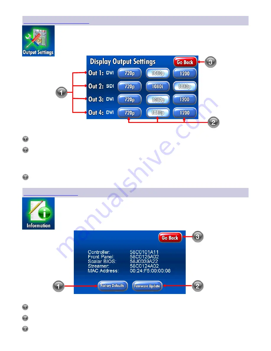
Choose
OUT 1
,
OUT 2
,
OUT 3
or
OUT 4
.
Select the desired output setting by touching the
720p
,
1080i
,
1080p
or
1200
button. The
1080i
option is available for
SDI
output modules only and the
1200
option is only available for
DVI
and
Fiber
Optic
output
modules.
Note:
If outputs 3 and 4 are
DVI
or
Fiber
and
SDI
, then the
DVI
or
Fiber
output
resolution cannot be set to
1200
.
Touch the
Go Back
button to return to the
Home
screen.
Touch the
Output Settings
icon on the home screen (page 9) to display the
Display
Output Settings
screen.
Information Screen
Touch the
Information
icon on the
Home
screen (page 9) to display the
Information
screen. This screen displays general information about your ConductOR. See the screen
shot below.
Touching the
Factory Defaults
button restores the ConductOR’s factory settings.
Touching the
Firmware
Update prepares the ConductOR to receive a firmware update.
Touch the
Go Back
button to return to the
Home
screen.
Содержание ConductOR
Страница 1: ...User manual E n g l i s h OR Informatics System...
Страница 2: ......
Страница 4: ......
Страница 58: ...51 Drawing and Dimensions 11...
Страница 65: ......


