background image

NAVMAN 

8120/8084 

 Installation and Operation Manual

73

Factory reset

This option returns all of the Instrument 
settings (except the language, waypoints and 
routes) to the default factory settings shown 
on the setup menus.

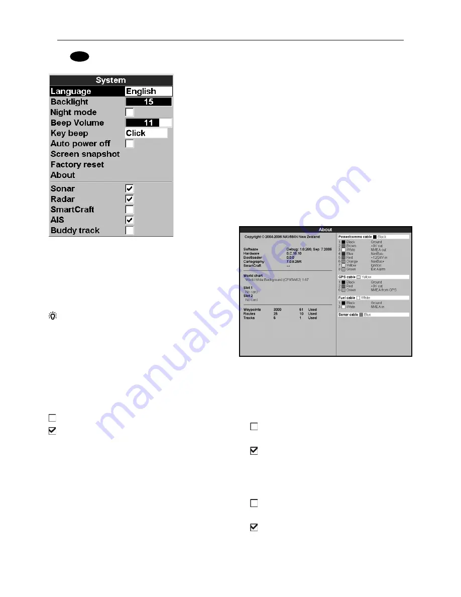
About

The about window shows:

•   The software version and date.

•   The world chart version.

•   Any card fitted.

•   The number of waypoints, routes and 

tracks you have stored.

•   Connector wiring information.

In the unlikely event of having to contact 
a NAVMAN dealer for service, quote the 
software version number and date.

Sonar


 Disable any sonar transducer and disable 

sonar functions.


 A sonar transducer is fitted. Enable sonar 

operation.

See section 19-3.

Radar


 No appropriate Radar system is fitted. 

Disable RADAR.


 An appropriate Radar receiver is fitted. 

Enable AIS.

See section 19-4.

19-1 Setup  > System

Press 

MENU

 twice, then select 

System

:  

Language

Select the language for the windows. The 
options are: English, Italian, French, German, 
Spanish, Dutch, Swedish, Portuguese, Finnish 
and Greek. 


Tip:

 In case you can’t read the current 

language, the language setting is found at 
the top of the system menu.

Backlight

Select the backlight level for the keys and 
display (see also section 2-3) 

Night mode

Night mode sets the palette for all windows

  Normal palette, for daytime

  All windows have a palette optimized for 

night time.

See also section 2-3. To change only the chart 
palette, see section 19-2.

Beep volume

Select the beep volume for key presses.

Auto power off

See section 2-2.

Содержание 8084

Страница 1: ...w w w n a v m a n c o m Installation and Operation Manual Navman 8120 8084...

Страница 2: ...without the safety alert symbol indicates a potentially hazardous situation which if not avoided may result in property damage As NAVMAN is continuously improving this product we retain the right to...

Страница 3: ...ion Chart 21 3 1 Introduction to navigating 21 3 2 Chart window 23 3 3 Distance and bearing calculator 25 3 4 Projected course 26 3 5 Tracks and tracking 26 4Videowindow 27 5Navigation Highwaywindow 2...

Страница 4: ...3 6 Fuel consumption curves 53 13 7 Calibration 55 14Tideswindow 56 15Usercardwindow 57 16AIS 59 16 1 Viewing AIS Vessels 59 16 2 Dangerous Vessels 60 16 3 AIS Windows 60 17DSC Buddytrackwindows 62 17...

Страница 5: ...ries 93 20 3 Installation The display unit 94 20 4 Installation Power data cable 96 20 5 Installation GPS antenna 97 20 6 Installation Sonar transducer 98 20 7 Installation NAVMAN petrol gasoline sens...

Страница 6: ...features on this chart plotter are designed as a safety aid only and do not guarantee safety at sea AIS transmission is mandatory on some but not all vessels You should check your local laws and regu...

Страница 7: ...th a user card 15 User card Chart data Chart features built in world chart 3 2 Chart details 3 2 4 5 Chart card Tides at a port 14 Chart card AIS 16 Alarms Built in alarms 2 5 Boat data Data at top of...

Страница 8: ...nd on the optional sensors and instruments that are installed The Video window requires the 8120 8084 to receive video from a compatible source such as a camera Fuel functions require one or more petr...

Страница 9: ...art window You can plug in up to two chart cards at once If the chart shows a region not covered by a chart card then it displays a simplified built in world chart 2 User cards store navigation data A...

Страница 10: ...84 turn each locking collar anticlockwise until you can pull the plug out 4 Store the 8120 8084 in a dry clean place Replacing the display unit 1 Plug the connectors into the back of the display unit...

Страница 11: ...y Cursor keys to move the cursor or the selection highlight u The key selects which window you are working with The Active window is indicated with a red border i The key allows you to quickly switch...

Страница 12: ...plays for easy access from the key e MENU Show a menu of the options for the current active window The setup menu can be opened by pressing MENU twice r ENTER Start an action or accept a change t Chan...

Страница 13: ...ve the highlight to the command for example Goto cursor then press ENTER Changing data First press or to move the highlight to the data to change then a To change a tick box means On or Yes means Off...

Страница 14: ...off You can now turn the Instrument off manually 2 3 Backlight and night mode To go to the Backlight window press briefly Backlight The display and keys are backlit To change the backlight level selec...

Страница 15: ...position as a waypoint called MOB 2 The Instrument changes to the chart window with the MOB waypoint at the centre of the chart The chart zooms in for accurate navigation If the chart can not show th...

Страница 16: ...strument ignores data from the GPS antenna and other transducers and sensors and the Instrument generates this data itself Otherwise the Instrument functions normally There are two simulate modes Norm...

Страница 17: ...120 8084 Installation and Operation Manual 17 To show one of the other windows full screen press DISPLAY select More and select the window Press ESC to return from one of these windows to the previous...

Страница 18: ...a red border 2 Press DISPLAY and select Delete window Exchanging two windows on the display 1 Press until the first window has a red border 2 Press DISPLAY select Replaceand select the second window...

Страница 19: ...ith six favorites Adding a favorite display to the list 1 Set up the display with the window or windows you want in the new favorite see sections 2 7 1 and 2 7 4 2 Press DISPLAY and select Save this d...

Страница 20: ...or select None to leave the field empty iii Repeat the above step to set the other data fields Tip If all fields in a line are None then the line will not be displayed and the data header will take l...

Страница 21: ...chart or highway windows b or use navigation data displayed on the data header see section 2 7 3 c or use COG and BRG on the compass see section 2 7 4 Note 1 If the XTE alarm is enabled an alarm will...

Страница 22: ...ds the next waypoint on the route Navigating The Instrument navigates to the point as described in section 3 1 1 Cancelling navigating Go to a Chart window press MENU and select Cancel goto Tip Before...

Страница 23: ...ea J The cursor see section 3 2 1 K A typical waypoint see section 6 Note To change the types of information displayed on the chart see section 17 2 To change to a perspective view of the chart see se...

Страница 24: ...in the data header The window is degrees and minutes to three decimal places about 2 m 6 ft resolution Normally the position is the boat s position and the latitude and longitude has a boat symbol to...

Страница 25: ...y objects that are not on the chart such as other boats The radar overlay is also very useful in conditions of reduced visibility at night or in busy or hazardous waters The range rotation mode and ce...

Страница 26: ...manually along the reference track back into the harbour Record reference tracks in good conditions 3 5 Tracks and tracking When recording is on and the track becomes full then recording continues and...

Страница 27: ...press DISPLAY and select Video Adjusting the video picture colour 1 Press MENU 2 Press or to highlight a control then press or to adjust the control 3 To return the colors to their default settings s...

Страница 28: ...of a danger waypoint the unit can sound an alarm see section 19 10 A display option Controls how the waypoint is displayed on the chart see section 19 2 5 Navigation Highway window The highway window...

Страница 29: ...ee section 6 2 7 Creating a new waypoint from the waypoints window 1 In the waypoints window press MENU and select Create 2 A new waypoint with a default name and data is created at the boat position...

Страница 30: ...ypoints window press or to highlight the waypoint to delete Press MENU and select Delete 2 Select Yes to confirm 6 2 6 Deleting all waypoints 1 In the waypoints window and press MENU and select Delete...

Страница 31: ...art and end at waypoints If a leg does not start or end at an existing waypoint then a new waypoint will be created automatically to change the new waypoint data see section 6 2 1 You can not use a Da...

Страница 32: ...emove a waypoint from the route i Move the cursor to the waypoint to remove from the route ii Press MENU and select Remove The waypoint is removed from the route but the waypoint is not deleted 5 To s...

Страница 33: ...1 In the routes window press or to highlight the route to edit Press MENU and select Edit 2 The selected route is displayed the route name and a list of the waypoints 3 Edit the route as described in...

Страница 34: ...eceived by the Instrument s standard GPS antenna The accuracy of the corrected GPS position is typically better than 5 m 15 ft for 95 of the time WAAS covers all of the USA and most of Canada EGNOS wi...

Страница 35: ...ving COG is a line from centre 9 Sonar fishfinding Introduction Sonar functions require an optional sonar transducer to be installed and set up This section explains how to interpret the sonar display...

Страница 36: ...crolled towards the left eventually disappearing off the window The scroll speed depends upon the water depth and scroll speed setting See sections 19 3 and section 9 2 for more information The appear...

Страница 37: ...is dependent upon the frequency of the pulse at 50 kHz it is approximately 45 and at 200 kHz it is approximately 11 The differences in the cone width affect what is displayed See section 9 3 Strength...

Страница 38: ...Hz The 200 kHz frequency is especially suitable for use in shallow and medium depth water typically less than 500 ft 150 m and while running at speed At 200 kHz the narrow cone reduces any noise cause...

Страница 39: ...dow compared to the 200 kHz frequency This means that a group of small fish for example could be displayed as a single item while any fish very close to the bottom may not be found at all This frequen...

Страница 40: ...8084 Installation and Operation Manual 40 50 kHz display 200 50 Khz display Mixed display 1 minute ago Comparison of the same fish scenario displayed at different frequencies 30 seconds ago Now 200 k...

Страница 41: ...ood conditions a fish passing through the cone shaped ultrasonic pulse is displayed as a fish arch The 50 kHz frequency uses a wider cone than the 200 kHz frequency This makes the fish arches easier t...

Страница 42: ...commended for normal operation To set Auto mode 1 Go to a sonar window see section 9 2 Press MENU select Range then Auto Manual The Instrument does not adjust the range automatically If the bottom dep...

Страница 43: ...the maximum signal are ignored There is a separate threshold setting for each sonar frequency 50 kHz and 200 kHz The gain window To display or change the current settings for gain select a sonar windo...

Страница 44: ...plus a bottom trace in a zoomed section see section 10 3 Split 50 200 Sonar histories at 50 and 200 kHz see section 10 4 10 Sonar fishfinding Windows 10 1 Sonar history window no split A Optional data...

Страница 45: ...t screen in the recorded history History position bar B A D E C These windows show a zoomed section of the sonar history The Sonar Zoom display shows the sonar history on the right and the zoomed sect...

Страница 46: ...lose to the bottom The zoom bar on the far right shows the area of the history that is magnified in the zoom section Use the or keys to adjust the zoom range The Instrument calculates the zoom depth a...

Страница 47: ...0 kHz A B C D E 3 Press MENU select Sonar splits then select Split A scope 4 Press ENTER to display the Gain window To adjust gain or threshold for a frequency press or to select the setting to adjust...

Страница 48: ...t 1 Select the layout to change see above 2 Press MENU and select Gauge setup 3 Highlight the gauge to change Press ENTER and select the data to display in the gauge 4 Repeat the above step to change...

Страница 49: ...lay press DISPLAY select More then select Fuel The display differs according to the number of engines and tanks If engine RPM is available and if you have made and selected a Fuel Consumption Curve se...

Страница 50: ...lti engine boat the data for the port engine is on the left of the display Use the flows to check the load of each engine Range The estimated boat range at the current fuel flow The value can depend o...

Страница 51: ...low speeds 13 5 Boat speed sensors To select an optional speed sensor 1 Press MENU twice select Fuel then select Speed source 2 To use a paddlewheel or pitot sensor select Water speed otherwise select...

Страница 52: ...ts For this example If the boat travels for one hour uses 3 gallons of fuel and has 50 gallons of fuel left Speed Log Economy Range Using water speed 10 knots 10 nm 3 3 nm gal 165 nm Using ground spee...

Страница 53: ...Normally choose Water speed to measure the boat s potential performance 3 Press MENU twice then select Fuel 4 Select Fuel consumption curve then select New 5 Enter the comfortable maximum RPM you know...

Страница 54: ...see sections 13 5 1 and 13 5 c More information about fuel consumption curves is available in NAVMAN s Diesel flow sensors installation and operation manual Using a curve Compare your boat s performan...

Страница 55: ...ficult to fill underfloor tanks to the same level twice due to air pockets so the more fuel used the more accurate the calibration 13 7 Calibration To calibrate the sensor s 1 Record the level of the...

Страница 56: ...date press ENTER A Tide station name and distance from boat B Current time and chosen date for display C Tide chart D Night E Dawn F Day G Dusk H Tide height I Time cursor a vertical dotted line Press...

Страница 57: ...aypoints which have the same names as existing waypoints Rplc all Load all new waypoints which have the same names as existing waypoints the new waypoints replace the existing waypoints The user card...

Страница 58: ...ess MENU and select Delete 3 Select Yes to confirm Rereading the file information This reads the file names from the user card and displays them Reading does not load any file data into the Instrument...

Страница 59: ...urn and type of vessel This unit can receive and display AIS information when connected to an AIS receiver Available AIS vessels transmitting in the local area are shown on the chart when this feature...

Страница 60: ...t a vessel 2 Press and select Display The Instrument switches to chart window with the selected vessel position in the middle 16 2 Dangerous Vessels The 8120 8084 calculates the time of closest point...

Страница 61: ...eceiver Sorting Vessels Press select Sort and select one of the options This sorts the list based on the chosen category Safety msgs rx Safety msgs rx are broadcasted messages received by the AIS rece...

Страница 62: ...have manually polled on the VHF radio and their position at that time Buddy track Buddy boats from your DSC radio The radio regularly calls the boats and updates their positions When your DSC radio re...

Страница 63: ...t A distress message creates a waypoint for the boat or you can create a waypoint at a polled boat s position To change the data of these waypoints 1 Press or to select a boat 2 Press MENU and select...

Страница 64: ...alled the PPI Plan Position Indicator Typically your boat is in the centre of the radar window with concentric range rings surrounding it The range rings help you to quickly estimate the distance to v...

Страница 65: ...s how long this will take 4 When the warm up period is complete the radar enters standby mode and is ready to transmit To start the radar transmitting see Section 18 4 18 4 Selecting standby mode or t...

Страница 66: ...r you operate at that range again 18 6 2 Changing the gain level Use the radar gain level to adjust the sensitivity of the radar receiver Ideally the radar gain level should be set so that background...

Страница 67: ...ain clutter is set too low there will be excessive rain clutter displayed whenever it s raining If the rain clutter is set too high very large targets such as the coastline will appear to be hollow To...

Страница 68: ...e a trail If the radar motion mode is relative any target that is moving relative to your boat will leave a trail 18 8 Turning the target trails on or off To change the target trails setting 1 From th...

Страница 69: ...s the EBL bearing relative to magnetic North or true North 5 Select Set centre to move the VRM and EBL centre away from your boat Use the arrow keys to move the centre so that it is aligned over the f...

Страница 70: ...ters or exits a specified area around your boat You can customize the size and shape of the radar guard zones and set up alarms 1 From the radar window press MENU then select Guard zone 18 11 1 Turnin...

Страница 71: ...guard zone in degrees BRG The bearing of a line drawn from your boat through the centre of the radar guard zone in degrees 4 Use and to select the parameter to change 5 Then use and v to change the pa...

Страница 72: ...The setup data available will depend on the optional sensors and instruments installed System Setup see section 19 1 Sonar Setup see section 19 3 Radar Setup see section 19 4 GPS Setup see section 19...

Страница 73: ...eration See section 19 3 Radar No appropriate Radar system is fitted Disable RADAR An appropriate Radar receiver is fitted Enable AIS See section 19 4 19 1 Setup System Press MENU twice then select Sy...

Страница 74: ...t redraw SmartCraft No SmartCraft gateway is fitted Disable SmartCraft functions SmartCraft gateway is fitted Enable SmartCraft operation See section 20 9 AIS No appropriate AIS receiver is fitted Dis...

Страница 75: ...t asks if you want to apply the NMEA datum offset see below WARNING Map shift is for eliminating minor offsets It should not be used if the correct datum is available Use map shift with caution incorr...

Страница 76: ...grid Boundaries Displays boundaries around areas where more detailed chart coverage is available Auto shows the next four detail levels On shows all Text icon size Select the size of chart text and i...

Страница 77: ...t will be displayed as a fish symbol and to trigger the Fish alarm The options are Small Medium and Large Fish sensitivity Selects the minimum strength fish echo that will be displayed as a fish symbo...

Страница 78: ...a longer pulse There is a choice of Auto Short Medium or Long The Auto setting is recommended Pulse power This can be used to specify the power output of the transmitted ultrasonic pulse Low power ou...

Страница 79: ...mpare the visual view in front of your boat with the radar screen Course up works only when COG data or heading data from a heading sensor is available and there is an active route It means that your...

Страница 80: ...radar image is aligned with the displayed chart and the compass An accurate bearing alignment is particularly important when the radar image is overlaid onto the chart Adjust this on a chart window w...

Страница 81: ...lowly the calculated GPS speed and course become erratic Static navigation allows the erratic values to be filtered 0 01 to 99 9 If the boat speed is slower than this the speed is displayed as zero an...

Страница 82: ...the engine is connected to Flow filter Most engines do not draw fuel from the tank at a steady rate To give a stable fuel flow reading the 8120 8084 calculates the flow by taking several measurements...

Страница 83: ...ect which to use for fuel calculations see section 10 5 1 Max fuel flow The maximum fuel flow from a fuel tank to be displayed on an analog fuel flow gauge see section 8 Max RPM The maximum engine RPM...

Страница 84: ...charts Filter by Type Vessel types that are not selected will be filtered off the chart Default is set to all types enabled allowing all vessels to be displayed on the chart Filter by distance Vessel...

Страница 85: ...istance to zero Reset engine hours Use this option to reset the engine hours to zero This can be useful after an engine service or to count the engine hours between service intervals Projected Course...

Страница 86: ...ger value XTE Boat moves o course by more than the CDI scale see section 5 Danger Boat comes closer to a danger waypoint than the alarm trigger value Too shallow 1 5 sec Depth is less than the alarm t...

Страница 87: ...or ImpGal Imperial Gallons Compass T True north or M Magnetic north Temperature F Fahrenheit or C Celsius Wind optional Requires a wind instrument True or App Apparent Note that the units for wind sp...

Страница 88: ...o fluctuate slightly To give stable readings the Instrument calculates these values by taking several measurements and averaging them Set the Speed filter to the lowest value which gives stable readin...

Страница 89: ...lay by adding the keel offset to all measured depths A Have a zero keel offset to display depths below the transducer B Enter a positive keel offset to increase the displayed depth For example to disp...

Страница 90: ...ation from the boat position press ESC to switch to centre on boat mode To start the simulation from a different point move the cursor to that point on the chart Tip To calculate a course use the curs...

Страница 91: ...ng of the boat To help ensure proper operation do not mount any part or cable within 0 5 m 20 of the plane of a radar antenna or within 1 m 3 ft of a compass or source of electrical noise such as engi...

Страница 92: ...display unit Power cable Mounting bracket and locking knobs Bracket mounting screws 5 x14 Gauge self tapping screws Flush mounting screws 4 x 8 Gauge self tapping screws NAVMAN wallet Contains the fo...

Страница 93: ...sors fitted to one or two engines NAVMAN petrol gasoline sensors see section 20 7 20 2 Installation Options and Accessories NAVMAN diesel sensors see section 20 8 SmartCraft fuel sensors see section 2...

Страница 94: ...the display will not be subjected excessive vibration Select an area with adequate clearance for cabling and access to the power source Before drilling any holes ensure that the drill area is free fro...

Страница 95: ...ables to the rear of the unit before placing the unit into the console 7 Firmly secure the unit in place with the 4 x 8 gauge self tapping screws Note the 5 x 14G self tapping screws are for bracket m...

Страница 96: ...the connector Power data cable Yellow Red Black Ignition Ignition switch Main switch 12 24 V DC Fuses 2A Power data cable Red Yellow Black 20 4 Installation Power data cable Main switch 12 24 V DC Fu...

Страница 97: ...AN dealer DGPS Source Enables or disables the satellite based DGPS correction see section 8 The options are None or WAAS EGNOS Do not Enable WAAS EGNOS outside their coverage areas or the accuracy of...

Страница 98: ...wo diesel flow sensor cables in parallel Normally power the diesel sensors from the boat ignition switch Then the Instrument does not need to be wired for auto power see section 18 4 During setup a se...

Страница 99: ...erefore NAVMAN fuel sensors are not required as well If the fuel tank does not have SmartCraft level sensors wire for auto power see section 20 4 During setup enter the SmartCraft setup data For infor...

Страница 100: ...fected If an alarm sounds mute it by clearing the alarm on any instrument which can display that alarm NavBus and the Instrument The 8120 8084 can Display wind speed and direction from an optional NAV...

Страница 101: ...d C MAP chart card see section 1 3 4 Turn the instrument on see section 2 2 When the Instrument is turned on for the first time it displays an installation menu i Select the language to use ii Change...

Страница 102: ...p shift Chart scale 0 05 to 4096 nm for chart chart dependent down to 0 01 nm in plotter mode SONAR FISHFINDING Optional sonar transducer required Depth range 1 m 3 ft to 1000 m 3300 ft Sonar output P...

Страница 103: ...NAVMAN 8120 8084 Installation and Operation Manual 103 NAVMAN 8120 Physical Dimensions NAVMAN 8084...

Страница 104: ...Indian 1960 Indian 1975 Indonesian 1974 Ireland 1965 ISTS 061 Astro 1968 ISTS 073 Astro 1969 Johnston Island 1961 Kandawala Kerguelen Island 1949 Kertau 1948 Kusaie Astro 1951 L C 5 Astro 1961 Leigon...

Страница 105: ...k to the manufacturer for repair Please follow this troubleshooting section before contacting the nearest NAVMAN dealer There are no user serviceable parts Specialized methods and testing equipment ar...

Страница 106: ...simulate mode Turn simulate mode off see section 19 16 c Local time offset is wrong see section 17 12 The Local Time Offset must be changed when daylight saving time starts or ends 2 6 Autopilot not...

Страница 107: ...n see section 19 6 3 5 There is no reading for fuel economy a The boat must be travelling through the water to generate an Economy reading b Check that the paddlewheel on the transducer is spinning fr...

Страница 108: ...detected A display of the bottom should reappear when in shallower water 4 3 The bottom is displayed too far up the screen The Instrument may have Manual Range selected and the selected Range value i...

Страница 109: ...of the radar window often producing a spiral effect Generally the stronger the interference the wider the interference lines a Use the interference rejection feature to reduce interference patterns an...

Страница 110: ...barometric pressure The more fishes that show the higher the likelihood requires NAVMAN 7200 VHF radio Gear The gear the engine is in requires SmartCraft Goto A simple way of navigating straight to a...

Страница 111: ...tion the 8120 8084 is navigating to either a waypoint or the cursor User card A plug in card that stores waypoints routes and tracks see section 1 2 UTC Universal Time Coordinated or Coordinated Unive...

Страница 112: ...OG Course Over Ground Direction in which the boat is moving over the ground CTS Course To Steer Optimum course to steer to return to the plotted course DTG Distance To Go Distance from the boat to the...

Страница 113: ...by turning the equipment o and on the user is encouraged to try to correct the interference by one or more of the following measures Reorient or relocate the receiving antenna Increase the separation...

Страница 114: ......

Страница 115: ...4 842 2F 1118 15 Janglim1 Dong Saha Gu Busan Korea Ph 82 51 293 8589 Fax 82 51 265 8984 e mail info kumhomarine com web www kumhomarine com Japan PlusGain Inc 1 A 324 3 Matunoki Tyou Takayama City Gif...

Страница 116: ...Lon 174 44 535 E Lat 36 48 404 S Made in New Zealand MN000444C G Navman 8120 8084 Installation and Operation Manual...

Отзывы: