background image

36        System Details

4.4.8    Accessing Advanced Menu Items

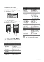
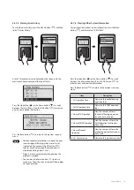
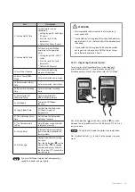
4.4.8.1   Viewing Service Information

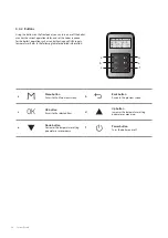
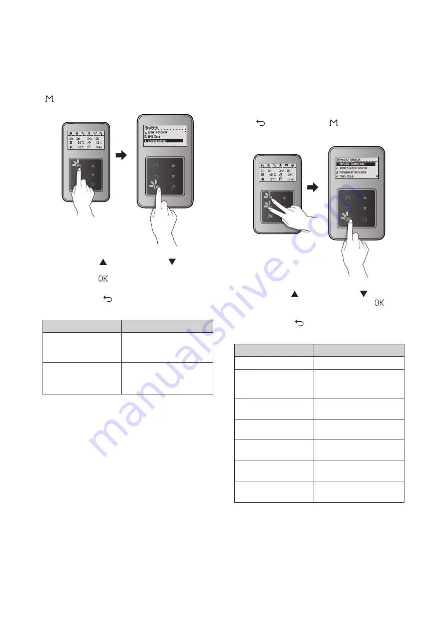
To view the service information about the boiler, press the Back 

button (

) and the Menu button (

) simultaneously for 

3 seconds, and then select “1. Service Status Info”.

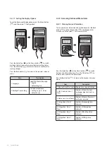
Press the Up button (

) or the Down button (

) to switch 

between the information items. Press the OK button (

) to 

select an item and view the information.

Press the Back button (

) to return to the previous screen or 

menu.

Item

Description

1. Elapsed Time After Install Elapsed time since installation

2. HEX Overheat - No. of 

Times

Number of times the heat 

exchanger high limit stat has 

activated

3. Flame Loss - No. of Times Number of times a flame loss/

misfire has occurred

4. 2nd ignition - No. of 

Times

Number of second ignition 

attempts

5. 3rd ignition - No. of 

Times

Number of third ignition 

attempts

6. 4th ignition - No. of 

Times

Number of fourth ignition 

attempts

7. 5th ignition - No. of 

Times

Number of fifth ignition 

attempts

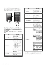
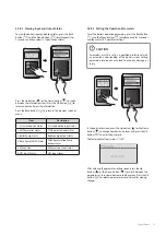
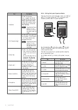
4.4.7.7   Setting the Display Options

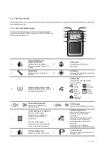
To set the front panel display options, press the Menu button  

(

), and then select “7. Configuration”.

Press the Up button (

) or the Down button (

) to switch 

between the list items or to increase/decrease setting values. 

Press the OK button (

) to select an item or to confirm after 

making changes.

Press the Back button (

) to return to the previous screen or 

menu.

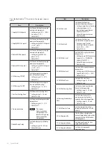
Item

Description

1. Language

Select the display language.

1. English


Default: English

5. Backlight Time Setting

Set the backlight time.


Setting range: 0 – 60 sec


Default: 2 sec

Содержание NCB-700-2S+/42K

Страница 1: ...co uk For warranty service always contact an official Technical Assistance Service TAS first Contact the technician or professional who installed your boiler Contact a Gas Safe Registered engineer Wh...

Страница 2: ...trol or other flammable vapours and liquids in the vicinity of this or any other appliance WHATTO DO IFYOU SMELL GAS Do not try to light any appliances Do not touch any electrical switch do not use an...

Страница 3: ......

Страница 4: ...Revisions 3 Version Description of changes Date 1 00 First issue July 11 2022 Revisions...

Страница 5: ...Expansion tank 60 5 Troubleshooting 61 5 1 Error Code Classification 61 5 2 Error Code List and Actions 62 5 2 1 Error 001 65 5 2 2 Error 003 67 5 2 3 Error 004 73 5 2 4 Error 012 74 5 2 5 Error 016 7...

Страница 6: ...upplier or distributor not authorised by Navien Failure to perform regular maintenance misuse operation at settings other than those recommended or specified non compliance with instructions or guidel...

Страница 7: ...as LP Propane Gas AP Air Pressure APS Air Pressure Sensor DHW Domestic Hot Water FM Fan Motor GARC Gas Air Ratio Control LPM Litre Per Minute MGV Main Gas Valve RPM Revolutions per Minute PCB Printed...

Страница 8: ...bour s phone call your gas provider and follow their instructions If you cannot reach your gas provider call the fire department Do not return to your home until authorised by your gas supplier or the...

Страница 9: ...explosion Do not place combustibles such as newspapers or laundry near the boiler or flue system Doing so may result in a fire Do not place or use hair sprays spray paints or any other compressed gas...

Страница 10: ...C Very low scald risk CAUTION Do not turn on the boiler unless the water and gas supplies are fully opened Doing so may damage the boiler Do not turn on the water if the cold water supply shut off va...

Страница 11: ...staining pressure of up to 3 bar The air vent is required in the system during filling CAUTION The boiler is equipped with an internal bypass valve The internal bypass valve is not intended to replace...

Страница 12: ...actice which is available from the Heating and Hotwater Industry Council who manage and promote the Scheme Visit www centralheating co uk for more information UKCA EC Conformity Declaration 0086 2797...

Страница 13: ...NCB700 3S 54K 35 0 kW 52 0 kW By default the boiler assigns system priority to DHW supply The NCB700 Series boiler has a built in circulation pump 3 way valve assembly flow sensor DHW plate heat exch...

Страница 14: ...ollowing diagram shows the key components of the boiler Component assembly diagrams and particular parts lists are included in the Appendices Fan Motor Front Panel Flue Duct Ignitor Flame Rod Circulat...

Страница 15: ...Mixing Chamber Expansion Vessel Primary Heat Exchanger Secondary Heat Exchanger Return Adapter Filter Assembly Secondary Circulation Pump 3 Way Valve Central Heating Return Pressure Relief Valve Cent...

Страница 16: ...Product Information 15 NCB700 3S 54K Fan Motor Front Panel Flue Duct Ignitor Flame Rod Circulation Pump Condensate Trap PCB...

Страница 17: ...Mixing Chamber Expansion Vessel Primary Heat Exchanger Secondary Heat Exchanger Return Adapter Filter Assembly Secondary Circulation Pump Gas Valve Central Heating Return Pressure Relief Valve Centra...

Страница 18: ...n Seasonal efficiency rate SEDBUK 2009 93 61 93 51 NOx Classification Class 6 Category ll2H3P Type Heating and instantaneous hot water production Heat output adjustment Adjustable over entire Max Min...

Страница 19: ...horizontal coaxial length 60 100 m 20 Max vertical coaxial length 60 100 m 21 Equivalent elbow length 90 60 100 m 2 4 Equivalent elbow length 45 60 100 m 1 2 Max horizontal coaxial length 80 125 m 68...

Страница 20: ...m 440mm Supply Connections Description Diameter A Flue exhaust Air intake 60 100 80 125 B Central heating supply 22 mm C Hot water outlet DHW 15 mm D Gas supply inlet 22 mm E Cold water inlet DHW 15 m...

Страница 21: ...P Switches Dip Switch Set of 2 The DIP SW on the front panel configures the fuel selection 1 2 O N Switch Function Setting 1 2 Fuel selection LNG G20 1 OFF 2 OFF Not Used 1 OFF 2 ON LPG G30 1 ON 2 OFF...

Страница 22: ...e with BS 6891 Installing of a LPG installation should only be done by a registered LPG installer The tank must be provided with a high pressure regulator with a minimum capacity of 24 kg h to reduce...

Страница 23: ...ed to minimises the risk of fire or explosion or to prevent property damage or personal injury The qualified service agency is responsible for the proper installation of this kit The installation is n...

Страница 24: ...ex nut here Figure 3 Detaching Gas Inlet Pipe from Gas Valve and Fan Motor Assembly Once the Gas Orifice is exposed remove the two screws that hold the part in place Remove the Gas Orifice from its ho...

Страница 25: ...onal injury WARNING Do not adjust or attempt to measure gas valve outlet pressure The gas valve is factory set for the correct outlet pressure This setting is suitable for natural gas and propane requ...

Страница 26: ...rly seated inside the port before proceeding to the next step 11 Replace the gas inlet pipe to its original position and use all screws to secure all connections Note Do not overtighten as this may da...

Страница 27: ...erate and proceed Gas Setup Wizard Note For proceeding Gas Setup Wizard for gas type selection refer to 4 4 4 Set Up Wizard on page 29 Measure the CO value at low fire If the CO value is not within 0...

Страница 28: ...boiler s schedule programming operation is set f DHW preheat Displayed when the DHW preheat feature is enabled DHW preheat DHW Intelligent DHW preheat Always on DHW preheat Weekly DHW preheat off Eco...

Страница 29: ...eating and DHW supply temperatures Refer to the following table for detailed information a b c d e f a Menu button Access to the Main menu screen b Back button Access to the previous screen c OK butto...

Страница 30: ...n the front panel display after the power is turned on 4 4 4 Set Up Wizard The setup wizard should run the first time the unit is powered on The wizard must be completed before the boiler can be used...

Страница 31: ...on or the Down button until the desired temperature appears on the display You can adjust the temperature while the display is flashing Once the display stops flashing the temperature setting is store...

Страница 32: ...ware version Note The fan motor controls the APS so the fan target speed Fan Target RPM is only for your reference 4 4 7 Accessing Basic Menu Items In the Main Menu screen you can view the boiler s op...

Страница 33: ...kdays Saturdays and Sundays 4 OFF NotUsed Disable the schedule function When the boiler is connected to an outdoor temperature sensor optional functioning may be activated according to outdoor tempera...

Страница 34: ...Set will be displayed The graph shows how the set temperature is determined K factor values can be set using the front panel 20 15 10 5 0 10 15 20 25 5 20 30 40 50 60 50 70 80 90 4 3 5 3 2 5 2 1 5 1 2...

Страница 35: ...HW usage for repeat the detected cycle 3 ECO Schedule Set the detect DHW usage for a week 4 Always Preheat Always turn on the DHW Preheat If you select DHW Schedule you can select the certain day to s...

Страница 36: ...he preheat operation function has been used 6 Gas Consumption View monthly gas consumption 4 4 7 5 Viewing Error History To view the error history press the Menu button and then select 5 Error History...

Страница 37: ...mes Number of times a flame loss misfire has occurred 4 2nd ignition No of Times Number of second ignition attempts 5 3rd ignition No of Times Number of third ignition attempts 6 4th ignition No of Ti...

Страница 38: ...itch between the parameters or to increase decrease setting values Press the OK button to select a parameter or to confirm after making changes 4 4 8 2 Viewing Input and Output Status To view the boil...

Страница 39: ...side in the DHW tank or DHW pipe line 19 Anti Legionella day Set the day of week for Anti Legionella operation 20 Anti Legionella time Set the Anti Legionella operation time Press the Back button to r...

Страница 40: ...years 22 Service Notify Cycle Set the service notification according to the operating times Setting range 300 36500 cycles It can be set in 100 cycle increments Default 18200 cycles 23 Low Water Pres...

Страница 41: ...d state the fan speed gradually increases and reaches the maximum speed at 6500 RPM and then the fan speed decreases until the fan stops operating Note Except for the Power button the buttons do not w...

Страница 42: ...S W RETURN_Temp SUPPLY_Temp Dip s w 8pin Dip s w 4pin BURNNER HTL M 7 6 5 4 3 2 1 8 MIX V V CN10 OUTLET_Temp 5 4 3 6 2 CN12 M HTL APS INLET_Temp 2 3 4 CN8 1 CN2 M 7 6 5 4 3 2 1 8 WAV V V CN11 P E 1 2...

Страница 43: ...t Valve Flow Control DC15V Vent Separation Detector Supply Thermistor Outlet Thermistor 1 Return Thermistor UART Communication Interface FRONT PANEL Communication Interface FUSE Inlet Thermistor 1 EMI...

Страница 44: ...the unit Fault PCB malfunction Symptoms A system component may not operate and generate an error code In most PCB failures the boiler will not operate until the fault is resolved Error codes E515 E61...

Страница 45: ...ll activate the high limit switch Fault Unable to detect high water temperature conditions if the switch malfunctions Symptoms Unable to shut down the boiler if the water temperature from the heat exc...

Страница 46: ...s are secure and inspect for wire damage 2 Test the resistance of the sensor Before testing shut down the boiler and allow it to cool Testing inspection information Resistance range Refer to the table...

Страница 47: ...y 0 rpm 2 A fan assembly screw is loose and or the fan is disassembled 3 Disconnected or defective fan connection terminal assembly Symptoms 1 Erratic combustion 2 Vibration and noise coming from the...

Страница 48: ...ite the gas 2 Results in multiple unsuccessful ignition attempts Symptoms 1 The boiler does not ignite and error code E003 or E004 is displayed 2 The durability of the igniter reduces Error codes E003...

Страница 49: ...toms 1 The boiler does not ignite and error code E003 or E004 is displayed 2 Durability of the transformer wears down Error codes E003 E004 Diagnostics 1 Visual inspection Check wire connections are s...

Страница 50: ...enerated Error codes E110 Diagnostics 1 Visual inspection Check wire connections are secure and inspect for wire damage 2 Voltage test Test the voltage meets the specifications shown below 3 Check the...

Страница 51: ...o prevent unsafe situations Fault Unable to open close Symptoms 1 No flame 2 The boiler does not operate Error codes E003 E012 Diagnostics 1 Visual inspection Check wire connections are secure and ins...

Страница 52: ...Unable to initiate or sustain combustion 2 Dust or soot deposits form on the burner s surface 3 Gas leakage from the burner Symptoms 1 Abnormal combustion 2 Unstable flame conditions and or flame loss...

Страница 53: ...ble to detect or measure water flow rate 2 Damage to and or leakage from the water flow sensor Symptoms 1 Ignition does not start 2 Boiler operation stops when water leakage is detected Error codes E4...

Страница 54: ...amber are used to minimise heat loss Fault 1 Water and or exhaust gas leaks 2 Scale deposits in the heat exchanger can cause water in the boiler to bubble Symptoms 1 Exhaust gas leaks 2 Overheating of...

Страница 55: ...he combustion chamber which minimises heat loss Fault 1 Water and or exhaust gas leaks 2 Scale deposits in the heat exchanger can cause water in the boiler to bubble Symptoms 1 Exhaust gas leaks 2 Ove...

Страница 56: ...ger filters the water in the space heating system to prevent faults in other parts of the heating system Fault 1 Water leaks 2 Low temperature water in the heat exchanger Symptoms DHW leaks and or tem...

Страница 57: ...ure water flow Symptoms 1 Water inside the boiler system freezes 2 Water temperature fluctuations when the boiler is set to internal recirculation 3 Hot water takes a long time to be available at taps...

Страница 58: ...toms DHW supply stops and flow continues in the space heating system when the space heating water temperature is lower than the set point Error codes E016 Diagnostics 1 Visual inspection Check the 3 w...

Страница 59: ...o detect or measure changes of water pressure Symptoms The water top up system does not operate automatically Error codes E351 E352 E353 Diagnostics 1 Visual inspection Check the circulation pump s wi...

Страница 60: ...ing gases Fault 1 Blades will not close 2 Blades will not open Symptoms 1 Boiler operation starts and stops frequently because of excessive heat supply 2 Set point temperature is not reached because o...

Страница 61: ...escription Function 1 Removes air from the system during heating 2 Relieves system pressure caused by expansion as the water temperature increases 3 Uses a built in low level water sensor to maintain...

Страница 62: ...operation Water pressure sensor Auto DHW Circulation E407 DHW Outlet thermistor Open or Short Circuit Alarm E421 DHW Inlet thermistor Open or Short Circuit Auto E434 Abnormal operation Flow control v...

Страница 63: ...als on the heat exchanger 6 Adjust the anti short cycle time E016 0 Heat exchanger overheat 1 Turn OFF the boiler wait at least 30 min and then restart the boiler 2 Clean the inlet water filter and st...

Страница 64: ...thermistor short error E291 3 Supply Return inversion limit Check the direct water connection E302 0 Low water pressure 1 Check the feeder valve 2 Check the incoming water pressure and activity at the...

Страница 65: ...l communication Check the PCB E783 0 Abnormal operation OpenTherm remote control E787 1 Abnormal operation Reset device E788 0 Abnormal operation Gas type settings E791 0 NaviCirc Vavle Open error E79...

Страница 66: ...e circulation pump Run it in test mode 2 Check the operation of the 3 way valves Run it in test mode 3 Check if the heating strainer is obstructed 4 Check if the main heat exchanger or the DHW heat ex...

Страница 67: ...r is obstructed by debris 2 Identify the type of debris caught in the strainer aluminium oxidised steel etc to help identify the cause of the obstruction Heating or DHW heat exchanger is obstructed 1...

Страница 68: ...and grounding 6 Check if the air pressure hose is broken or obstructed 7 Check if the air pressure sensor is operating correctly 8 Check the PCB DIP switch settings 9 Adjust the offset pressure 10 Ch...

Страница 69: ...e correct Is the gas valve open Check the flame rod Turn OFF the boiler Check that the gas valve is open or check the LP supply Check the connections Test the voltage between WHITE YELLOW at CONZ1 DC...

Страница 70: ...overtightened An overtight connection can deform the seal and obstruct the flow of gas 5 Check the class of pressure meter Digital pressure manometer Check gas supply pressure Deformed seal can obstr...

Страница 71: ...ks in the insulator Adjust the gap if discharge is visible Ensure that the insulating gasket is fitted between the electrode and burner casing Check the input voltage at the ignition transformer AC 23...

Страница 72: ...etween theYELLOW WHITE wires and verify the voltage is DC 24 V 2 If there is no voltage replace the PCB 3 If the voltage is correct check if the coil is open Check the resistance Check if the solenoid...

Страница 73: ...case Use a multimeter to test the spark current normally 3 4 A Test the spark current connectors Ground connection Flame loss and noise occurs at ignition Check for obstructions in the gas orifice pla...

Страница 74: ...ied within the correct pressure range 4 Check the PCB and replace if faulty Is there burner flame when there is no ignition External noise interference Clean or replace the flame rod Check the current...

Страница 75: ...2E is displayed manually cleared on the front panel Checklist 1 Use a manometer to measure the gas supply pressure NG 17 25 mbar LP 25 35 mbar 2 Check the gas meter rating 3 Tighten the ground connect...

Страница 76: ...bustion 3 Check the gas pipe connections If a CSST connector has been used ensure that it has not been overtightened An overtight connection can deform the seal and obstruct the flow of gas 4 Check th...

Страница 77: ...auses Testing method Other faults PCB DIP switch setting errors Check the PCB DIP switch settings Check the correct resistance for flame detection AD PCB fault If the error conditions continue after c...

Страница 78: ...urge and starts the circulation pump Checklist 1 Check the overheat controller is working correctly Test the resistance or continuity 2 Check the hot water temperature sensor 3 Test the circulation pu...

Страница 79: ...ured at levels lower than it actually is test to confirm if the temperature sensor is faulty Check the output temperature displayed on the front panel 2 Measure the temperature sensor resistance and d...

Страница 80: ...oller detects the exceeding temperature of 110 C for 10 minutes or more E030 is displayed and a post purge will be performed Automatically cleared 2 When the controller detects the exceeding temperatu...

Страница 81: ...Defective overheat controller Faulty terminals on the exhaust gas overheat controller 110 C max Check the overheat controller s wiring connections If the resistance is incorrect replace the temperatu...

Страница 82: ...stance within the normal range Replace heat exchanger thermistor Check connections Step 1 Flush clean Filter Step 2 Restart Step 3 Replace PCB Yes Yes No No 5 2 9 Error 047 Error Conditions and Checkl...

Страница 83: ...enturi test mode 2 Check that the wiring harness is connected correctly and the cables are not damaged Is the dual venturi closed Does the dual venturi repeatedly open and close Replace the controller...

Страница 84: ...djusting is complete 4 Enter the dual venturi test mode and perform a test 1 Repeat the test at least twice Turning the unit ON and OFF once is one test cycle ON OFF ON OFF is the minimum sequence 2 C...

Страница 85: ...ombustion and the boiler switches to Lock out mode The air volume sensor should be normal Checklist 1 Check if the fan motor works normally using the component test mode 2 Test the power supply to the...

Страница 86: ...structions below to replace the fan 1 Unplug the boiler s power cable and wait 10 sec for all remaining SMPS voltage to completely discharge 2 Disconnect the fan cable and then re connect it 3 Reconne...

Страница 87: ...condensation drain line and drain for obstruction 3 Check the flue and exhaust are installed correctly and have adequate clearance The circulation of exhaust gas generates noise 4 Check if the air su...

Страница 88: ...the old PCB with the latest version Condensate drain error Condensate drain error Exhaust air is blocked due to condensate drain faults Check if the condensate hose or the siphon is frozen Check if th...

Страница 89: ...ector is wet due to any reason including leakage 2 Replace the defective heat exchanger output temperature sensor 3 Check the circulation pump s operating status and the flow rate in the space heating...

Страница 90: ...sor is faulty if the resistance is 30k or higher Replace the temperature sensor if the resistance value is abnormal Check the temperature displayed on the front panel Possible Issues Circulation pump...

Страница 91: ...lays 218E on the front panel If this occurs the boiler initiates shutdown Checklist 1 Check if the heat exchanger input temperature sensor connector is wet due to any reason including leakage 2 Replac...

Страница 92: ...esistance of the temperature sensor The sensor is faulty if the resistance is 30 k or higher Replace the temperature sensor if the resistance value is abnormal Check the temperature displayed on the f...

Страница 93: ...f the input water pressure sensor is wet for any reason including leakage 2 Check the auto feeder 3 Check the controller Is there a leak inside the boiler Is the water pressure sensor normal Check con...

Страница 94: ...the input water pressure sensor is wet for any reason including leakage 2 Check the controller Is there a leak inside the boiler Is the water pressure sensor normal 1 Check connections Repair the leak...

Страница 95: ...essure sensor is wet due to any reason including leakage 2 Replace the water pressure sensor 3 Check the controller Is there a leak inside the boiler Is the water pressure sensor normal 1 Check connec...

Страница 96: ...ected the system displays the 407E error on the front panel Check items 1 Check if the hot water temperature sensor connector is wet due to any reason and if the connector is connected properly 2 Chec...

Страница 97: ...0k or higher Replace the temperature sensor if the resistance value is abnormal Check the temperature displayed on the front panel Possible Issues Defective PCB If the issues continue despite checking...

Страница 98: ...e system displays the 421E error on the front panel Check items 1 Check if the cold water temperature sensor connector is wet due to any reason and if the connector is connected properly 2 Check if th...

Страница 99: ...or Check the resistance of the temperature sensor Defective if it is 40k or higher Replace the temperature sensor if the resistance value is abnormal Check the temperature displayed on the front panel...

Страница 100: ...valve Check the Fan voltage 1 Check the wire connection between dual venturi and Main controller 2 Check the dual venturi 1 Turn off and on the Power RESET switch 2 In that same case replace the Main...

Страница 101: ...k items Check the PCB Error occurrence conditions and check items Fault Possible Causes Check method E594 Error Abnormal communication by PCB 1 Click the Reset button on Front panel 2 Turn the POWER t...

Страница 102: ...from Reset Curve Mode to Normal Mode Check items 1 Check the parameter setting 2 Check the outdoor sensor Is the Outdoor sensor installed properly Is the outdoor thermistor normal Check connecter Cha...

Страница 103: ...set the unit at MIN 1 If noise occurs at standard value adjust setting above below the standard 2 Gas supply error due to defective air pressure sensor 3 If the same error is repeated it is due to a d...

Страница 104: ...boiler The cold water temperature sensor may not be working properly Low hot water temperature Hot water setting error Check the hot water temperature setting on the front panel Water mixed with cold...

Страница 105: ...if the wire is fixed and properly attached on the main side of the heat exchanger Circuit breaker trips Normal assembly Short circuit due to defective assembly Wiring near the heat exchanger Circuit...

Страница 106: ...ormance and operation after the boiler has been serviced To remove and replace any parts from the boiler you will need a screwdriver that is at least 8 10 inches long A flashlight and magnetic tip are...

Страница 107: ...zard and change to the existing setting 11 When the boiler is turned on press the Back button and the Menu button simultaneously for 3 seconds and then select 3 Parameter Settings On the password scre...

Страница 108: ...nd gas supply to the unit Note Do not over tighten the screws for the fan motor replacement with high torque drill This may cause damage to the part s 6 2 3 Fan Motor Combustion Air 1 Turn off the gas...

Страница 109: ...ly power supply and gas supply to the unit Note Verify that the Ignition Transformer insulated cables are firmly connected to the flame rod 6 2 4 Flame Rod 1 Turn off the gas supply to the unit 2 Disc...

Страница 110: ...Turn off the water supply to the unit 4 Refer to figure11 and remove the air pressure sensor wiring connector Figure 11 5 Remove the hose from the air pressure sensor Figure 12 6 Remove the 2 screws t...

Страница 111: ...11 Replace the front panel to its original position 12 Turn on the water supply power supply and gas supply to the unit Note Ensure that the condensate drain trap is completely inserted into the conde...

Страница 112: ...isconnect the unit from the power supply 3 Turn off the water supply to the unit 4 Loosen the central heating return pipe adapter Figure 16 5 Remove the 4 screws and clip at the bottom of the cover Fi...

Страница 113: ...tight seals 6 Remove the flow control valve and sensor 7 Replace it with the new flow control valve and sensor 8 Turn on water supply power supply and gas supply to the unit 9 Carefully open a hot wa...

Страница 114: ...gas supply to the unit 2 Turn off the 230V power supply to the unit 3 Turn off the water supply to the unit Drain all water from the appliance 4 Remove the gas supply unit 5 Remove the two screws at...

Страница 115: ...Remark 1 Cover 30030074A 2 Panel 30029172A 3 Controller 30028548A 4 Siphon 30029038A 5 Adapter 30029966A 6 Wind pressure sensor 30025533B 7 Tank 30029045A 8 Inlet adapter 30029947A 9 Valve 30030507A 1...

Страница 116: ...transformer 30029732A 5 Fuse 30025036A 6 Dual venturi 30029315A 3S 54K 30029314A 2S 42K 7 Outlet adapter 30029538A 8 Inlet adapter 30013743A 9 Clip 20007733B 10 Electrode 30030059A 11 Packing 2005191...

Страница 117: ...upply pipe 30029104A 9 Temperature sensor 30022222B 10 O ring 20033699A 11 Valve 30011532B 12 Clip 20033662A 13 Supply pipe 30029104A 14 3 way valve 30020637A 15 Heat exchanger 30029328A 30029327A 16...

Страница 118: ...ing the Return Filter YES NO Checking the Intake Air Filter YES NO Flushing the Heat Exchanger YES NO Replacement of Parts 8 3 Maintenance Schedules Owner maintenance Daily Check boiler area Check pre...

Страница 119: ...Memo...

Страница 120: ...Memo...

Страница 121: ...Memo...

Отзывы: