System Details 23
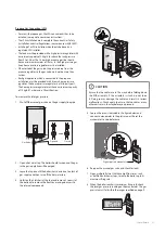
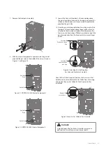
9. Loosen the hex nut at location A - the connection above
the gas valve where it connects to the pipe. See Figure 3 for
reference. Once the hex nut is loose, carefully separate the
pipe from the gas valve.
10. Once the gas inlet pipe is detached from the gas valve, find
location B - the connection above the gas valve where it is
attached to the fan motor assembly. Carefully remove the
four screws by hand using a Phillips screwdriver and pull the
gas inlet pipe away from the fan assembly to access the gas
orifice.
Location B:
Remove 4 screws
here
Location A:
Loosen the hex
nut here
Figure 3. Detaching Gas Inlet Pipe from
Gas Valve and Fan Motor Assembly
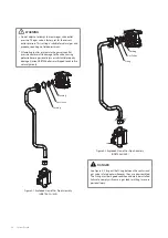
Once the Gas Orifice is exposed, remove the two screws that
hold the part in place. Remove the Gas Orifice from its housing
and prepare the new Gas Orifice for the LP conversion for
installation.
Remove 2
screws here
Figure 4. Access to Gas Orifice in Fan Assembly
DANGER
A high voltage in the Fan Motor Assembly may cause an
electrical shock resulting in severe injury or death.
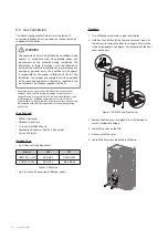
7. Remove the front panel assembly.
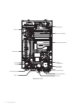
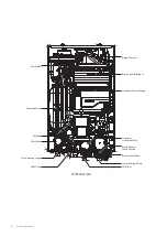
8. With the internal components exposed, locate the gas inlet
pipe and the gas valve in the middle of the unit, as shown in
Figure 2-1 and Figure 2-2.
Gas Valve
Gas Inlet
Pipe
Figure 2-1. NCB700-2S+/42K Internal Components
Gas Valve
Gas Inlet
Pipe
Figure 2-2. NCB700-3S/54K Internal Components
Содержание NCB-700-2S+/42K
Страница 3: ......
Страница 4: ...Revisions 3 Version Description of changes Date 1 00 First issue July 11 2022 Revisions...
Страница 119: ...Memo...
Страница 120: ...Memo...
Страница 121: ...Memo...

