


NX5 OPERATION & MAINTENANCE MANUAL
OPERATING THE TRANSMITTER
VERSION 0.1 2015-08-01
PAGE 3.2.25
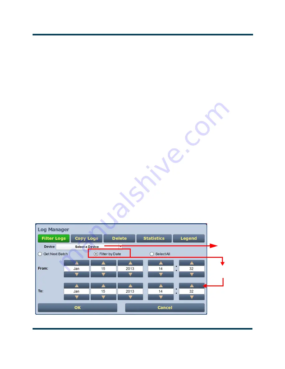
Filtering Logs
You can change which events are visible on the
Logs
screen based on the settings in the
Filter
Logs
tab in the Log Manager (see
).
Click the
Select a Device
drop-down arrow, and select the desired device type to restrict events shown
to only those originating from the selected device. Click the
OK
button or the
Cancel
button when
done.
No selection
- displays all transmitter events (shown as
Select a Device)
Controller
- displays controller events only
Exciter A or B
- displays applicable exciter events only
Rack #
- displays applicable Rack # events only
RF Module #
- displays applicable RF Module # events only
Click the
Get Next Batch
radio button to display the previously logged batch of events (up to 2000
items) for the device type selected. Click the
OK
button or the
Cancel
button when done.
Click the
Filter by Date
radio button to filter events based on a selected date and time range, and the
device type selected. Click the
OK
button or the
Cancel
button when done.
Click the
Select All
radio button (default) to show all of the most recent events in the current ‘bathc’for
the device type selected. A maximum of 2000 items (in 20 pages) can be displayed per ‘batch’. Click the
OK
button or the
Cancel
button when done.
Click the
Cancel
button to close this window and discard changes.
Figure 3.2.13: Log Manager - Filter Logs
Controller
Exciter A
Exciter B
Rack #
RF Module #
By Date/Time
Range
Содержание NX5 AM
Страница 2: ......
Страница 4: ......
Страница 8: ...NX5 OPERATION MAINTENANCE MANUAL PAGE 3 VIII VERSION 0 1 2015 08 01 ...
Страница 216: ...NX5 OPERATION MAINTENANCE MANUAL ROUTINE MAINTENANCE PAGE 3 3 12 VERSION 0 1 2015 08 01 ...
Страница 219: ......


