GV60 TROUBLESHOOTING MANUAL
RESPONDING TO ALARMS
VERSION 1.0 2018-01-01
PAGE 4.1.41
Power Supply or LVPS Module Fault Validation
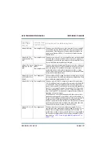
Each power supply and LVPS module has four LEDs on its front panel (see
in identifying a fault and allowing you to determine whether remedial action is required now or later.
Figure 4.1.12: Power Supply Module LEDs
Record which power supply modules are displaying an alarm and the state of its LEDs (see below).
AC OK LED
Green (solid): Ac voltage is present and within acceptable limits.
Green (blinking): Ac voltage is present, but outside acceptable limits.
DC OK LED
Green (solid): Power supply is enabled and output regulated.
Green (blinking): Power supply is experiencing an over-current condition.
SERVICE LED
Amber (solid): Power supply is experiencing a high temperature condition.
FAULT LED
Red (solid): Module is experiencing and internal fault.
Red (blinking): Communication has been lost with the rack controller.
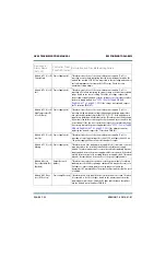
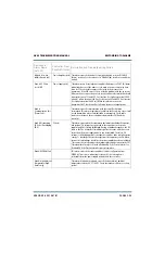
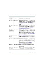
Other combinations of power supply module LEDs, and the corresponding power supply condition, are
listed in
.
Top of Power Supply Module
Содержание GV60
Страница 2: ......
Страница 4: ......
Страница 8: ...GV60 TROUBLESHOOTING MANUAL PAGE 4 VIII VERSION 1 0 2018 01 01 ...
Страница 102: ...GV60 TROUBLESHOOTING MANUAL PARTS LISTS PAGE 4 2 12 VERSION 1 0 2018 01 01 ...
Страница 463: ...VERSION 1 0 2018 01 01 MD 17 Figure MD 17 NAPA31C Power Amplifier PWB Q1 ...
Страница 466: ...VERSION 1 0 2018 01 01 MD 20 Figure MD 20 NAI23A RF Drive Splitter Changeover Assembly FRONT BACK ...
Страница 473: ...VERSION 1 0 2018 01 01 MD 27 Figure MD 27 NAL17 4 Input Reject Load Assembly TOP VIEW END VIEW 2 INPUT REJECT PWB A1 ...
Страница 475: ...GV60 TROUBLESHOOTING MANUAL LIST OF TERMS PAGE 4 6 2 VERSION 1 0 2018 01 01 ...
Страница 476: ......

