GV60 TROUBLESHOOTING MANUAL
RESPONDING TO ALARMS
VERSION 1.0 2018-01-01
PAGE 4.1.27
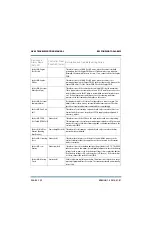
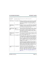
Module #: Missing
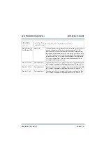
Power Amplifier (red) This alarm occurs if the RF power module is removed. If the associated RF
power module is present, and the alarm still occurs, try reseating the RF
power module. If the alarm persists, suspect a fault with circuitry on the
module control/interface PWB (A3). See also Rack #: Module Extraction
Shutback alarm.
Module #: No PAs
Operational (No PAs
Op)
Power Amplifier (red) This alarm occurs when all of the power amplifiers in the associated module
are inactive due to external conditions such as ac power loss, removal of
power supplies, or faults in the power supplies or power amplifiers. Check
for associated alarms and troubleshoot accordingly.
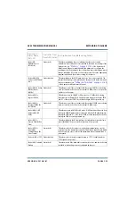
Module #: PA Current
Imbalance (PA Curr
Imb)
Output Network
(amber)
Power Amplifier (red)
This alarm occurs when the maximum PA current on one side of the power
module combiner exceeds 3.5 times the maximum PA current on the other
side of the combiner. This will latch off the module, since it indicates a
possible fault in the module combiner, transmitter combiner or output
network. If more than one module has this alarm, the transmitter will shut
down with a Combiner Match alarm.
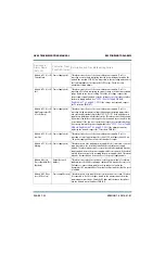
Module #: PA Volts A
(or B) Fail [PA V A (or
B) Fail]
Power Supply (red)
This alarm indicates the PA voltage from the power supply does not match
the requested setpoint. This is likely caused by a power supply failure. Check
the associated power supply module (A or B).
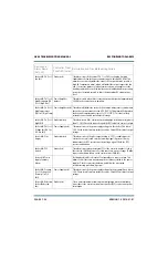
Module #: PA 1-4 Fail Power Amplifier (red) This alarm occurs if (1) the PA voltage for the suspect PA is greater than
16 V; (2) the RF drive level to the suspect RF power module (with failed PA)
is less than 10 W; and (3) if conditions (1) and (2) are met, the dc input
current for the suspect PA has fallen below a preset threshold (typically less
than 50% of the average PA current of the operational PAs). This may be
caused by a cabling fault on the PA, loss of PA voltage, bias voltage or RF
drive, or a defective FET. The transmitter’s output power may be reduced,
depending on the power setpoint.
The alarm can also occur after initiating a Xmtr PA Bias routine, which is
required after replacing an RF power module or the controller module. In
this case the alarm indicates that the bias routine failed for the specified PA,
possibly as a result of a PA bias circuit failure or an actual PA failure.
Attempt to operate the PA in the desired mode. If the fault clears, the alarm
was likely caused by a PA bias circuit fault. If the fault remains and/or the
PA current levels are below average, it is likely a PA failure
.
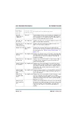
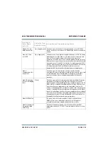
Module #: PS A (or B)
AC Fail
Power Supply (red)
This alarm occurs if one of the two module power supplies (1 or 2) is
reporting an ac failure, indicating its ac input voltage is less than 175 V ac.
If a bank of power supply modules are indicating an AC Fail alarm, it is
possible that an ac phase loss has occurred. Check the ac voltage applied to
the suspect power supply module. If the ac voltage is acceptable, replace
the module (see
“LVPS / Power Supply Module Replacement” on
).
Device and
Alarm Name
(AUI, UI)
Controller Front
Panel LED (color)
Description and Troubleshooting Action
Содержание GV60
Страница 2: ......
Страница 4: ......
Страница 8: ...GV60 TROUBLESHOOTING MANUAL PAGE 4 VIII VERSION 1 0 2018 01 01 ...
Страница 102: ...GV60 TROUBLESHOOTING MANUAL PARTS LISTS PAGE 4 2 12 VERSION 1 0 2018 01 01 ...
Страница 463: ...VERSION 1 0 2018 01 01 MD 17 Figure MD 17 NAPA31C Power Amplifier PWB Q1 ...
Страница 466: ...VERSION 1 0 2018 01 01 MD 20 Figure MD 20 NAI23A RF Drive Splitter Changeover Assembly FRONT BACK ...
Страница 473: ...VERSION 1 0 2018 01 01 MD 27 Figure MD 27 NAL17 4 Input Reject Load Assembly TOP VIEW END VIEW 2 INPUT REJECT PWB A1 ...
Страница 475: ...GV60 TROUBLESHOOTING MANUAL LIST OF TERMS PAGE 4 6 2 VERSION 1 0 2018 01 01 ...
Страница 476: ......


