GV60 TROUBLESHOOTING MANUAL
RESPONDING TO ALARMS
PAGE 4.1.52
VERSION 1.0 2018-01-01
1.
Use the transmitter’s AUI (local or remote) or controller UI alarm status/logs to isolate the defective
low voltage power supply (LVPS), noting there may be redundant (dual) supplies installed, or
Power Supply module.
2.
Open the transmitter front door and locate the suspect LVPS / Power Supply module. See
for cabinet A and
3.
or
Power Supply module from the front of the transmitter.
4.
Locate or obtain a replacement LVPS / Power Supply module (Nautel Part # UG92*).
5.
or
LVPS / Power Supply module.
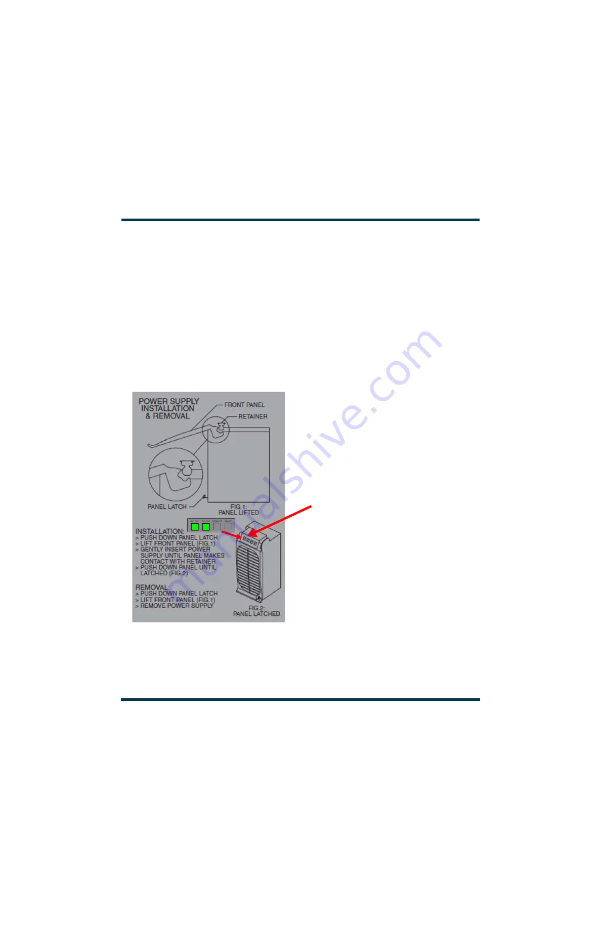
Figure 4.1.17: Removing/Installing LVPS / Power Supply Modules
AC OK
and
DC OK
LEDs should be on (green)
after successful power supply installation.
If the associated RF power module is disabled,
the
DC OK
LED will not turn on until the module
is enabled.
Содержание GV60
Страница 2: ......
Страница 4: ......
Страница 8: ...GV60 TROUBLESHOOTING MANUAL PAGE 4 VIII VERSION 1 0 2018 01 01 ...
Страница 102: ...GV60 TROUBLESHOOTING MANUAL PARTS LISTS PAGE 4 2 12 VERSION 1 0 2018 01 01 ...
Страница 463: ...VERSION 1 0 2018 01 01 MD 17 Figure MD 17 NAPA31C Power Amplifier PWB Q1 ...
Страница 466: ...VERSION 1 0 2018 01 01 MD 20 Figure MD 20 NAI23A RF Drive Splitter Changeover Assembly FRONT BACK ...
Страница 473: ...VERSION 1 0 2018 01 01 MD 27 Figure MD 27 NAL17 4 Input Reject Load Assembly TOP VIEW END VIEW 2 INPUT REJECT PWB A1 ...
Страница 475: ...GV60 TROUBLESHOOTING MANUAL LIST OF TERMS PAGE 4 6 2 VERSION 1 0 2018 01 01 ...
Страница 476: ......


