GV60 TROUBLESHOOTING MANUAL
RESPONDING TO ALARMS
VERSION 1.0 2018-01-01
PAGE 4.1.11
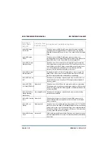
Controller: Cutback
Active
Output Network
(amber)
This alarm occurs whenever the transmitter experiences a cutback. A
cutback (reduction in power) occurs when repeated shutback alarms occur
within a prescribed time period. Shutbacks occur when the transmitter's
peak reflected power exceeds 2:1 due to a transient SWR condition (arc or
lightning) within the output transmission line or antenna system. The
transmitter shuts back and recovers to a series of cutback levels (depending
on the severity of the alarm), with each level being a 15% reduction in
power from the power attained before the last shutback. Inspect the output
transmission line for punctures or damage. After repairing damage, or if no
damage is found, attempt to reset the latched condition.
Controller: Digital
Player Audio Low
Exciter (red)
This alarms occurs if the audio player is in use on the SBC, but no digital
audio is detected by the controller.
Controller:
Discharging PA Volts
(Discharging PA V)
PS (red)
This alarm occurs when the transmitter has initiated a shutback sequence,
and residual PA voltage energy stored in the capacitors in the power
supplies and PAs is being discharged. During a shutback sequence, the RF
drive to the PAs is turned off immediately after the event, and this occurs
faster than the power supply modules can be inhibited. Therefore, PA
voltage is still being applied to the capacitors with no drive to discharge the
energy. To discharge the stored energy from the capacitors, the PA bias is
increased to a discharge level after the power supplies have been inhibited.
This causes the stored energy to be dissipated through dc current in the FET.
This alarm should only occur with a Residual PA Volts Present alarm. See
Residual PA Volts Present alarm for more information.
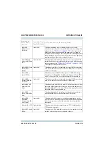
Controller: Door Open Exciter (amber)
This alarm occurs if the transmitter’s front door is open, which inhibits the
monitor cooling fans.
Controller: Entered
Firmware Upgrade
(Entr Firmware Upgr)
Exciter (red)
This alarm occurs when the transmitter is in “firmware upgrade” mode. It
should only be displayed during a transmitter software upgrade.
Controller: Exciter A
or B Offline
Exciter (red)
This alarm occurs if the serial communication fails between the controller
and the exciter, or a problem has occurred with the exciter. Check all
connections to the exciter and make sure that its controller front panel
power LED is on.
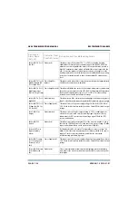
Controller: Exciter
Audio Reset
Exciter (red)
This alarms occurs if the audio processing within the exciter required a
reset. if this alarm is re-occurring, replace the controller (see
)
.
Controller: Exciter
Summary (Exciter
Summ)
Exciter (amber)
This alarms occurs if there are any exciter related alarms present. Check for
specific exciter related alarms.
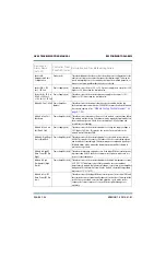
Device and
Alarm Name
(AUI, UI)
Controller Front
Panel LED (color)
Description and Troubleshooting Action
Содержание GV60
Страница 2: ......
Страница 4: ......
Страница 8: ...GV60 TROUBLESHOOTING MANUAL PAGE 4 VIII VERSION 1 0 2018 01 01 ...
Страница 102: ...GV60 TROUBLESHOOTING MANUAL PARTS LISTS PAGE 4 2 12 VERSION 1 0 2018 01 01 ...
Страница 463: ...VERSION 1 0 2018 01 01 MD 17 Figure MD 17 NAPA31C Power Amplifier PWB Q1 ...
Страница 466: ...VERSION 1 0 2018 01 01 MD 20 Figure MD 20 NAI23A RF Drive Splitter Changeover Assembly FRONT BACK ...
Страница 473: ...VERSION 1 0 2018 01 01 MD 27 Figure MD 27 NAL17 4 Input Reject Load Assembly TOP VIEW END VIEW 2 INPUT REJECT PWB A1 ...
Страница 475: ...GV60 TROUBLESHOOTING MANUAL LIST OF TERMS PAGE 4 6 2 VERSION 1 0 2018 01 01 ...
Страница 476: ......


