GV60 TROUBLESHOOTING MANUAL
RESPONDING TO ALARMS
VERSION 1.0 2018-01-01
PAGE 4.1.21
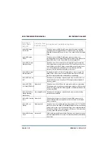
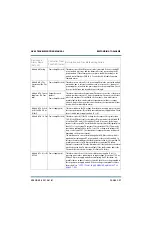
Controller: +5V B Fail Power Supply (red)
This alarm occurs if the sec5 V supply in the controller is 10%
lower or 10% higher than the desired value. Check the output voltage of
the LVPS module. If necessary, replace the LVPS (see
Supply Module Replacement” on page 4.1.50
.
There may also be a
problem with the controller’s power supply PWB.
Exciter A/B: AES
Digital 1 Audio Low
(Dig 1 Aud Low)
Exciter (amber)
This alarm indicates the Digital 1 input level is too low or is not applied. The
threshold and timing for this alarm can be adjusted in the Audio Low menu
in the user interface (see
“Setting User Thresholds” on page 3.2.168
of the Operations & Maintenance Manual.
Exciter A/B: AES
Digital 2 Audio Low
(Dig 2 Aud Low)
Exciter (amber)
This alarm indicates the Digital 2 input level is too low or is not applied. The
threshold and timing for this alarm can be adjusted in the Audio Low menu
in the user interface (see
“Setting User Thresholds” on page 3.2.168
of the Operations & Maintenance Manual.
Exciter A/B: Analog
Left (or Right) Low
(Anlg L or R Aud Low)
Exciter (amber)
This alarm indicates the analog left or right audio input level is too low or is
not applied. The threshold and timing for this alarm can be adjusted in the
Audio Low menu in the user interface (see
) of the Operations & Maintenance Manual.
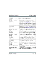
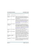
Exciter A/B: Audio
Processor Offline
(Audio Proc Offline)
Exciter (amber)
This alarm occurs if the exciter is configured to include an Orban Inside
audio processor, but it is not communicating with the processor on the
internal serial bus. Check all connections to the Orban Inside audio
processor card.
Exciter A/B: Audio
Processor Output Fail
(Audio Proc O/P Fail)
Exciter (amber)
This alarm occurs if the exciter is configured to include an Orban Inside
audio processor, but it is not detecting audio from the processor. Check all
connections to the Orban Inside audio processor card.
Exciter A/B: Audio
Shutdown
Exciter (red)
This alarm occurs if the exciter’s audio processing and FM modulation code
is shut down. Should display only during a software upgrade.
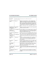
Exciter A/B: DSP
Audio Reset
Exciter (red)
This alarm indicates that the exciter has detected a misalignment in the
audio buffers and has restarted the audio processing in the DSP. If the
condition persists or re-occurs, this may indicate a fault with the exciter
hardware.
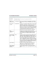
Exciter A/B: Entered
Firmware Upgrade
(Firmware Upgr)
Exciter (red)
This alarm occurs when the exciter is in “firmware upgrade” mode. It
should only be displayed during a transmitter software upgrade.
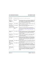
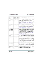
Exciter A/B: Exgine
Misconfigured
Exciter (red)
This alarm occurs when the Exgine is not configured properly for the current
operating mode. The alarm may occur briefly during a service mode change,
or may persist if the exciter cannot communicate with the Exgine. See the
troubleshooting action for the Exgine Offline alarm for more information.
Device and
Alarm Name
(AUI, UI)
Controller Front
Panel LED (color)
Description and Troubleshooting Action
Содержание GV60
Страница 2: ......
Страница 4: ......
Страница 8: ...GV60 TROUBLESHOOTING MANUAL PAGE 4 VIII VERSION 1 0 2018 01 01 ...
Страница 102: ...GV60 TROUBLESHOOTING MANUAL PARTS LISTS PAGE 4 2 12 VERSION 1 0 2018 01 01 ...
Страница 463: ...VERSION 1 0 2018 01 01 MD 17 Figure MD 17 NAPA31C Power Amplifier PWB Q1 ...
Страница 466: ...VERSION 1 0 2018 01 01 MD 20 Figure MD 20 NAI23A RF Drive Splitter Changeover Assembly FRONT BACK ...
Страница 473: ...VERSION 1 0 2018 01 01 MD 27 Figure MD 27 NAL17 4 Input Reject Load Assembly TOP VIEW END VIEW 2 INPUT REJECT PWB A1 ...
Страница 475: ...GV60 TROUBLESHOOTING MANUAL LIST OF TERMS PAGE 4 6 2 VERSION 1 0 2018 01 01 ...
Страница 476: ......


