National Cycle, Inc.
PO Box 158 Maywood, IL 60153-0158 USA
P: 708-343-0400 / F: 708-343-0625 / E: [email protected]
www.nationalcycle.com
©2021 National Cycle, Inc.
Page 09 of 13
10-118625-000 03/21
Illustration D
WIPER MOTOR INSTALLATION; CONT’D.
Illustration D
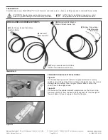
Once the Wiper Arm is on the Spindle, install the Internal Tooth Lock
Washer and Small Mounting Nut as shown in
Illustration D
.
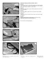
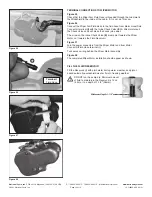
Figure 31
With a Torque Wrench and 13mm Socket, tighten the Small Mounting Nut
to 16 ft-lbs. (22Nm). Then swivel the mount cover of the Wiper Arm back to
its closed position.
Now take the Wiper Arm’s rubber hose and feed it through the Grommet
(D)
you installed in the Windshield in
Figure 25
.
REINSTALL THE VEHICLE WINDSHIELD
If you chose previously to uninstall the vehicle’s windshield prior to the
Wiper Motor installation, now is the time to reinstall it.
Follow the installation guide in
Windshield Installation
Instruction Sheet 10-118624-000.
Need the instructions? Go to
www.nationalcycle.com
and insert
N30214
into the search box on the top right of the home page.
Click the product listing, then click on the
N30214 Installation
Instructions PDF link
.
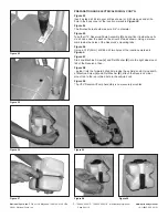
Make sure you install the additional Wraparound Clamp from
BAG#1368
as outlined on
Page 07
.
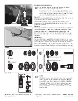
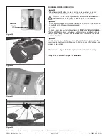
Figure 32
In
Figures 15A/15B
previously, you pulled the Wiring Harness of Motor
Hose/Fluid Connector Terminal
(I)
to follow the vehicle’s frame to the top
center where the Wiper Motor will be located. Now you will position the
Wiring Harness between the Windshield and the Wraparound Clamps to
secure them.
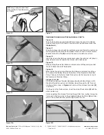
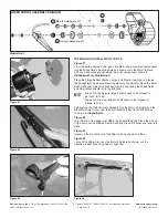
Figure 33
On the driver’s side, route harness wiring/fluid hose underneath Windshield
(inside of cab) but over the two side Wraparound Clamps as shown.
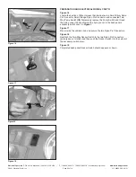
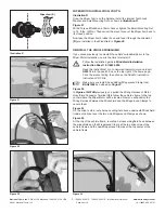
Figure 34
At the top of the vehicle frame, route the harness wiring/fluid hose between
the windshield and the Wraparound Clamp at the top driver-side of the
vehicle frame and the new Wraparound Clamps at the top center of the
vehicle frame
Figure 31
Figure 32
Figure 33
Figure 34
Wiper Arm (B)


