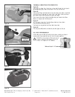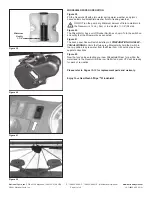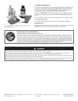
National Cycle, Inc.
PO Box 158 Maywood, IL 60153-0158 USA
P: 708-343-0400 / F: 708-343-0625 / E: [email protected]
www.nationalcycle.com
©2021 National Cycle, Inc.
Page 08 of 13
10-118625-000 03/21
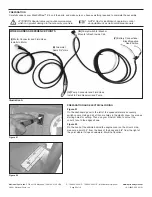
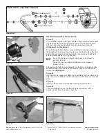
WIPER MOTOR ASSEMBLY DIAGRAM
Spindle Hardware Kit
M8 Stud Hardware Kit
Illustration C
Figure 27
WIPER MOTOR INSTALLATION; CONT’D.
Figure 27
From inside the vehicle’s cab, insert the Motor and assembled components
into the Windshield’s mounting holes as shown. Hold the Motor in place
with one hand while you assemble the
outer
components shown in
Illustration B
and
Illustration C
.
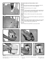
Place the Large Rubber Washer, Large Cup Washer (with the cup facing
the Windshield), and Large Mounting Nut onto the Spindle. Place the Small
Rubber Washer, Small Cup Washer (with the cup facing the Windshield),
and Small Mounting Nut onto the M8 Stud.
The nut on the Spindle (larger) shaft needs to be torqued to
4.5 ft-lbs. (6 N-m).
The nut on the stud (smaller) shaft needs to be torqued to
3 ft-lbs. (4 N-m).
Finally,place the Nylon Spindle Standoff onto the Motor’s Spindle, and the
Black Nylon Nut Cover over the Small Mounting Nut on the M8 Stud as
shown in in
Illustration B
.
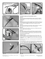
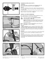
Figure 28
Join the end of the Wiper Arm
(B)
to the Wiper Blade
(C)
. Place the J-hook
of the Arm over the Blade’s plastic mounting clip until it clicks and locks into
place.
Figure 29
Swivel up the mount cover of the Wiper Arm as shown and then...
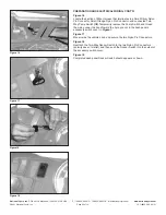
Figure 30
...mount the Wiper Arm over the Motor’s Spindle as shown. Let the
attached rubber hose hang free for right now.
Figure 28
Figure 29
Figure 30


