

National Cycle, Inc.
PO Box 158 Maywood, IL 60153-0158 USA
P: 708-343-0400 / F: 708-343-0625 / E: [email protected]
www.nationalcycle.com
©2021 National Cycle, Inc.
Page 02 of 13
10-118625-000 03/21
PREPARATION
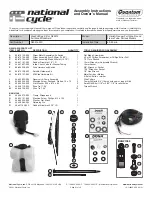
Carefully unpack your Wash'n'Wipe™ Kit, sort the parts, and make sure you have everything required to complete the assembly.
ATTENTION: Special notes and cautionary measures
which can prevent damage to the accessory or vehicle.
NOTE: Tips for facilitation of operation, control
and adjustment, as well as maintenance work.
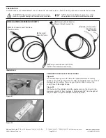
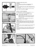
WIRE HARNESS REFERENCE POINTS
(V)
Battery Connections:
Black-Negative
Red-Positive
(III)
Pump Switch for Washer
Mounts to Dash Inside Cab
(I)
Motor Connector and Fluid Hose
Installs to Motor
(II)
Grommet
Seals 3/4" Hole
(IV)
Pump Connector and Fluid Hose
Install to Fluid Reservoir and Pump
Illustration A
Figure 01
Figure 02
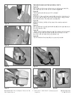
PREPARATION AND ELECTRICAL WIRING
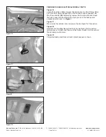
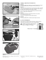
Figure 01
On the dashboard panel to the left of the speedometer are accessory
switch covers. Using a drill, drill some holes in the plastic cover to serve as
starting holes for cutting. Then use your X-Acto® knife to cut out the
cover’s face to the edges shown.
Figure 02
On the hood of the vehicle behind the engine cover on the driver’s side,
measure a point 4.5" from the back of the body and 5/8" from the right at
the point where it slopes downward. Mark that location.


