27
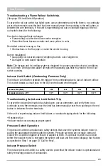
Gas Furnace
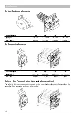
Furnace Size (Btuh)
25k
32k
43k
50k
Opens (in w.c.)
-0.15 +/- 0.05
-0.3 +/- 0.05
-0.3 +/- 0.05
-0.6 +/- 0.05
Closes (in w.c.)
-0.30 Max
-0.45 Max
-0.45 Max
-0.75 Max
Troubleshooting A Pressure Switch Trip
To check the pressure switch, first prove that the inducer assembly is pulling adequate static
pressure at the pressure switch tubing using a manometer.
To prove the pressure switch has welded closed, use an ohmmeter, and verify there is
continuity across the terminals when disconnected from the pressure switch tubing.
If the unit is experiencing faults with the pressure switch check for the following:
• Proper venter motor operation with no obstructions in the housing.
• Inspect the tubing for blockages, cracks, or other damage.
• Check the ports on the venter housing for blockage with corrosion or debris.
• Verify that the venter tubing is installed properly on the pressure switch (non-condensing
models gray – negative side).
• Look for a restricted flue or venter housing (mud wasps nests).
• Verify the inducer orifice is installed correctly and is the proper size (condensing models)
Inducer Assembly
The inducer assembly includes the inducer motor which is powered by 208-230 Volts AC from
the DSI control board terminals IND and Neutral.
On Non-Condensing Models the inducer motor and wheel are removed from the housing with
(3) 5/16" screws.
side).
•
Look for a restricted flue or venter housing (Mud Wasps nests).
•
Verify the inducer orifice is installed correctly and is the proper size (condensing models)
Inducer Assembly
The inducer assembly included the inducer motor which is powered by 208-230 volts ac from the DSI control board
terminals IND and Neutral.
On non condensing models the inducer motor and wheel are removed from the housing with 3 5/16” screws.
On condensing models the entire inducer assmebly must be disconnected from the flue pipe by loosening the the 5/16”
screw on the worm gear clamp that attaches the rubber connector to the pvc flue. Than 4 ¼” screws will need to be
removed to release the housing from the collector box.
Содержание CPG41838-U
Страница 2: ...2...
Страница 5: ...5 Unit Dimensions Original R22 with Gas Heat A B Series 43...
Страница 6: ...6 Original R22 with Electric Heat A B Series Unit Dimensions...
Страница 7: ...7 Unit Dimensions Original R410A with Gas Heat B C D E Series...
Страница 8: ...8 Unit Dimensions Original R410A with Electric Heat B C D E Series...
Страница 9: ...9 Unit Dimensions U Series R410A 80 Gas Heat...
Страница 10: ...10 Unit Dimensions U Series R410A up to 95 Gas Heat...
Страница 11: ...11 Unit Dimensions U Series R410A Electric Heat...
Страница 19: ...19 Gas Furnace 3 Remove the 11 screws 4 Remove the front furnace baffle...
Страница 46: ...46 Chassis Cooling Section...
Страница 79: ...79...


