National Comfort Product 1000 SERIES Скачать руководство пользователя страница 8

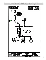
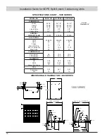
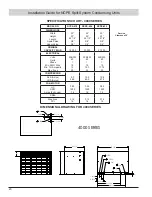
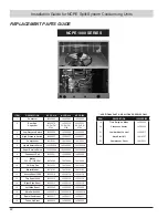
Installation Guide for NCPE Split-System Condensing Units

8


b.

  Provide a heat sink at the service valve such as wrapping 

a wet rag around it, to prevent damage during the brazing 

operation


c

.  Braze the liquid line to the service valve. Allow the nitrogen 

to keep flowing when brazing the refrigerant line until all 

brazed joints are completed.


d

.  Carefully remove the rubber plugs from the evaporator 

liquid and vapor connections. Use caution as the 

evaporator is pressurized.


e.

 Braze the liquid line to the evaporator liquid connection


f.

 Braze the vapor line to the evaporator vapor connection


g.

  Provide a heat sink to the vapor line service valve of the 

condensing unit


h.

 Braze the vapor line to the service valve


i.

   When  tubing  installation  is  completed,  seal  openings 

around tubing where tubing enters the unit cabinet.


j.

  Standard refrigeration piping practices must be employed 

when  installing  traps.  When  installing  the  condenser 

below the evaporator, the suction line must be trapped 

with an inverted trap the height of the evaporator coil. 

Consult the factory when total equivalent length of 

refrigerant lines exceeds 50 ft.

Leak Checking

Leak checking of refrigerant line braze joints and evaporator 

unit using dry nitrogen.
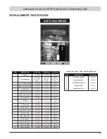
1.

 Install service port cap of the vapor line service valve (cap was 

removed for brazing operations).

2.

 Connect dry nitrogen source to the service port of the liquid 

line service valve. Pressurize refrigerant lines and indoor coil to 
approximately 100 PSIG.
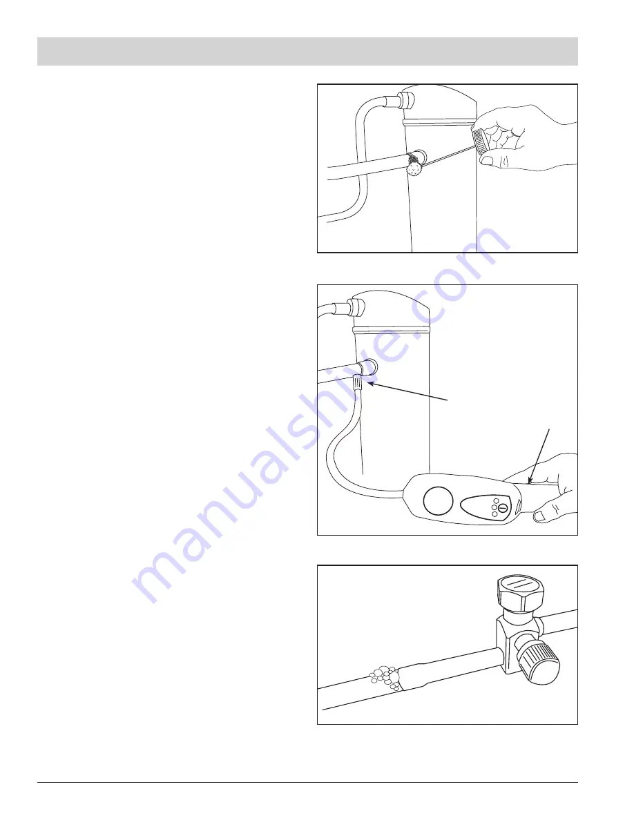
3.

 Check for leaks using a liquid soap solution. If any leaks are 

located, purge the nitrogen, repair the leak(s) and repeat the leak 

check procedure.

Leak checking of refrigerant line braze joints and evaporator 

unit using R410a refrigerant.
1.

 Connect R410a source to the service port of the liquid line 

service valve. Use of a manifold gauge set will facilitate connecting 

and disconnecting of the refrigerant source for leak checking. 

Pressurize refrigerant lines and indoor coil with refrigerant gas.

2. 

Leak check with an electronic leak detector or liquid soap 

solution. If any leaks are detected, use a refrigerant recovery 

system to remove the refrigerant. Repair the leak(s) and repeat 

the leak check procedure.

Apply liquid soap solution to check for leaks

or leak check with an 


electric leak detector

Bubbles forming in the liquid soap solution indicates a leak.

Содержание 1000 SERIES

Страница 1: ...639 1674 HEATING A C EQUIPMENT NATIONAL COMFORT PRODUCTS Thru the Wall Condensing Units This unit should be installed in an OUTSIDE WALL FOR THRU THE WALL INSTALLATION ONLY Please read the entire inst...

Страница 2: ...gh Voltage and Power Supply Page 10 Start Up Sequence of Operations Page 11 Refrigerant Charging Page 12 Maintenance Checkout Procedure Page 13 Important Before Removing a Warranty Compressor Page 14...

Страница 3: ...ntly grounded Failure to do so can cause electrical shock resulting in severe personal injury or death WARNING These instructions are intended as an aid to qualified licensed service personnel for pro...

Страница 4: ...instructions do not cover all variations in systems or provide for every possible contingency to be met in connection with the installation Should further information be desired or should particular...

Страница 5: ...of these decorative grilles The less resistive these grilles are to air flow the better the units performance will be Outdoor louvers provided by others must be approved by NCP to maintain unit perfor...

Страница 6: ...Liquid Line Pressure Drop 50 PSI Subtract 43 PSI for each foot of Liquid Lift if any Do Not Exceed this value when selecting Liquid Line Field Installation Install the units per the manufacturer s re...

Страница 7: ...the condensing unit should not block access to major components Refrigerant lines should not be in direct contact with the floor or ceiling joists Use insulated or suspension type hangers When refrig...

Страница 8: ...l equivalent length of refrigerant lines exceeds 50 ft Leak Checking Leak checking of refrigerant line braze joints and evaporator unit using dry nitrogen 1 Install service port cap of the vapor line...

Страница 9: ...aporator coil The vacuum pump can now be disconnected Electrical Connections NOTE Make certain that the volts hertz and phase correspond to that specified on the unit rating plate and that the service...

Страница 10: ...equipment nameplate OR Make certain that the volts hertz and phase correspond to that specified on the unit rating plate and that the service provided by the utility is sufficient to handle the additi...

Страница 11: ...ubcooling in cooling mode is the only recommended method of charging above 55 F ambient outdoor temperature For best results the indoor temperature should be kept between 70 F to 80 F Note It is impor...

Страница 12: ...lar CAUTION Low Suction Pressure Operation Compressor Damage Do not operate with a restricted suction Do not operate with the low pressure cut out bridged Do not operate compressor without enough syst...

Страница 13: ...age Check exposed surfaces for corrosion Replace or paint part as required This maintenance is critical to prevent stains and damage to exterior surface of building 5 Inspect refrigerant piping for le...

Страница 14: ...HM Reading between Terminals C R __________ 5 Compressor Winding OHM Reading between Terminals R S __________ 6 Compressor Winding OHM Reading between Terminals C Ground __________ 7 Compressor Windin...

Страница 15: ...Installation Guide for NCPE Split System Condensing Units 15...

Страница 16: ...Installation Guide for NCPE Split System Condensing Units 16...

Страница 17: ...Installation Guide for NCPE Split System Condensing Units 17...

Страница 18: ...10 15 3 25 208 230 60 1 10 17 75 30 Volts Hertz Phase Min AWG Wire Min Cir Ampacity Max Fuse COMPRESSOR 9 0 56 3 10 9 62 9 12 8 67 8 RLA Amps LRA Amps FAN MOTOR 0 25 1500 1 4 0 25 1500 1 4 0 25 1500...

Страница 19: ...12 13 20 208 230 60 1 10 15 3 25 208 230 60 1 10 18 56 30 Volts Hertz Phase Min AWG Wire Min Cir Ampacity Max Fuse COMPRESSOR 9 0 56 3 10 9 62 9 13 5 72 5 RLA Amps LRA Amps FAN MOTOR 0 25 1500 1 4 0...

Страница 20: ...NOMINAL CAPACITY B HR 18 000 23 000 27 200 ELECTRICAL 208 230 60 1 12 13 20 208 230 60 1 10 15 3 25 208 230 60 1 10 17 75 30 Volts Hertz Phase Min AWG Wire Min Cir Ampacity Max Fuse COMPRESSOR 9 0 56...

Страница 21: ...00 28 400 ELECTRICAL 208 230 60 1 12 13 47 20 208 230 60 1 12 15 13 20 208 230 60 1 10 19 08 30 Volts Hertz Phase Min AWG Wire Min Cir Ampacity Max Fuse COMPRESSOR 9 0 56 3 10 3 61 6 13 50 72 5 RLA Am...

Страница 22: ...ondenser Coil 14208361 14208360 14208360 9 Motor 0 25 HP 1500 RPM 14270049 14270049 14270049 10 14 Prop Fan 14214033 14214033 14214033 11 Motor Mount 14270102 14270102 14270102 12 Access Panel 1000 14...

Страница 23: ...denser Coil 14208356 14208357 14208357 9 Motor 0 25 HP 1500 RPM 14270049 14270049 14270049 10 14 Prop Fan 14214033 14214033 14214033 11 Motor Mount 14270102 14270102 14270102 12 Access Panel 3000 1425...

Страница 24: ...High Pressure Switch 14265027 14265027 14265027 5 Compressor 14210241 14210242 14210243 6 Liquid Service Valve 14258603A 14258603A 14258603A 7 Vapor Service Valve 14258606A 14258606A 14258606A 8 Conde...

Страница 25: ...8603A 14258603A 14258603A 7 Vapor Service Valve 14258612 14258612 14258612 8 Condenser Coil 14208372 14208371 14208371 9 Motor 14270056 14270056 14270056 10 Prop Fan 14214038 14214038 14214038 11 Moto...

Страница 26: ...As an option we offer an Insulated Sound Cover for installation over the inside cover of the unit Sound Without Indoor Cover 70 4 dba Standard AHRI 350 2008 Sound With Indoor Cover 68 3 dba Standard...

Страница 27: ...tional Comfort in specifications drawings or otherwise and whether or not National Comfort s goods are specifically designed and or manufactured by National Comfort for Customer s use or purpose 4 LIM...

Страница 28: ...ort after one year from the date of installation or after 20 months from the date of manufacture of the compressor as determined by the compressor serial number whichever occurs first but before the e...

Страница 29: ...essure with service door reattached ENGINEERING SPECIFICATION GUIDE 4 Technical Data Limitations All installations should factor a proper building heat gain along with appropriate duct sizing and elec...

Страница 30: ..._______________________ ________________________________________________________________________ ________________________________________________________________________ ______________________________...

Страница 31: ...______________________ ________________________________________________________________________ ________________________________________________________________________ _______________________________...

Страница 32: ...Comfort Products 539 Dunksferry Road Bensalem PA 19020 5908 800 523 7138 Fax 215 639 1674 HEATING A C EQUIPMENT NATIONAL COMFORT PRODUCTS Manual NCPE Condensing Unit Installation Instructions 14299118...

Отзывы: