


Installation Guide for NCPE Split-System Condensing Units
29
1. Product Name
National Comfort Products
–
Thru the Wall Condensing Units
2. Manufacturer
National Comfort Products
539 Dunksferry Road, Bensalem, PA 19020
Phone: (800) 523-7138:
Fax: (215) 639-1674
Email:
Website:
www.NationalComfortProducts.com
3. Product Description
Thru the wall condensing units are designed for the
multi-family industry. The thru the wall operation saves
money and time with simple installation. No long refrigerant
or electrical runs, no ground clutter, no theft or vandalism,
no roof penetrations and the unit can be easily service
indoors.
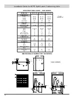
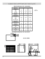
Models
1000 Series Condensing Unit – 12 SEER - 26 ¼" x 28 5/8" x 18 ½"
3000 Series Condensing Unit – 12 SEER – 24 1/8" x 32" x 18 ½"
3000 Series Heat Pump – 12 SEER – 24 1/8" x 32" x 18 ½"
4000 Series Condensing Unit – 12 SEER – 30" x 23" x 22 ½"
5000 Series Condensing Unit – 14 SEER – 39" x 27" x 18 ¼"
Capacities
1 ½ , 2 , & 2 ½ ton for condensing units
1 ½ & 2 ton for heat pumps
Materials
Cabinet to be constructed of Pre-Painted Galvanized Steel
Condenser coil shall be fabricated of raised lanced
aluminum fins mechanically bonded to seamless rifled
copper tubes.
Color –
Neutral tone finish of Tan
Voltage
Factory wired for 208-230 V, single phase, 60 Hz with low
voltage rated 24 V, 60 Hz Class 2 transformer not included
with condensing unit.
Service Valves
Brass with ability to check operating pressure with service
door reattached.
ENGINEERING SPECIFICATION GUIDE
4. Technical Data Limitations
All installations should factor a proper building heat gain,
along with appropriate duct sizing and electrical supply
wiring to be figured by a professional engineer familiar with
local and national codes.
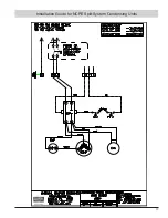
5. Standard Controls & Components
Equipped to operate with a standard singles stage
thermostat (2 stage heat pump thermostats required for
3000 Series Heat Pumps only). All units equipped with high
efficiency scroll compressors and propeller style condenser
fan design.
6. Install
Recommended installation with wall sleeve for clean finish
and future service accessibility. Provide minimum of 30”
in front of unit for service access and proper distances from
all outside utilities in accordance with all local and national
codes. A minimum vertical clearance of 48” between
units should be maintained to minimize recirculation of
condenser air.
7. Sales
National Comfort Products condensing units and matched
air handlers are dealt thru a variety of wholesalers. Contact
the factory to help locate a nearby distributor for price and
availability.
8. Warranty
2 year warranty of all parts and 5 year warranty of the
compressor. 90 days labor warranty.
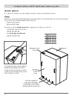
9. Service
The units can be easily serviced from indoors and should
be properly maintained in accordance of the manufactures
instructions. All standard maintenance instructions are within
the installation guide.
10. Technical Support
Factory technical assistance is available to help with
any concerns or situations regarding National Comfort
Products.


