


Installation Guide for NCPE Split-System Condensing Units
7
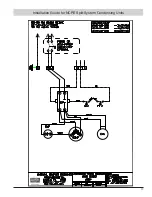
Step 3:
Flux the copper tube and insert into the stub. Braze
the joint. No flux is necessary if a low to zero-silver
braze alloy is used.
Step 4:
After brazing, quench with a wet rag to cool the
joint and remove any flux residue. Evacuate,
purge or charge the connecting lines per the unit
manufacturer’s instructions.
Step 5:
This is not a back seating valve. To open the valve
remove the valve cap with an adjustable wrench.
Insert a 3/16” or 5/16” hex wrench into the stem.
Back out counter-clockwise until the valve stem just
touches the retaining ring.
Step 6:
Replace the valve cap finger tight then tighten an
additional 1/12 turn or 1/2 hex flat. A metal-to-metal
seal is now complete. Complete normal factory
recommended procedure
s.
1.
The unit has internally mounted service valves. Field tubing
may be routed through the locations provided in either the top or
rear flange. Care should be taken not to block access to internal
components. Seal unused knockouts with high grade sealant.
Gaskets are provided for liquid and suction lines.
Note: Always use refrigeration grade copper
tubing that is internally clean and dry for
refrigerant lines. Use clean hard drawn copper
tubing if no appreciable amount of bending is
necessary. If soft copper is used, avoid sharp
bends which may cause a restriction. Always
use heat sink materials during brazing to
prevent damage to service valves (See Page 6).
2.
Run refrigerant lines as directly as possible. Field piping
inside the condensing unit should not block access to major
components. Refrigerant lines should not be in direct contact
with the floor or ceiling joists. Use insulated or suspension type
hangers. When refrigerant lines run through a wall, seal openings
around the lines with a flexible material to avoid vibration to the
structure.
3
. Insulate the vapor line with a minimum 1/2
"
foam rubber
or other type insulation having an adequate vapor barrier. For
indoor units with a TXV, a liquid line filter drier must be installed
(SPORLAN #C-083-S or similar).
Caution: Dry nitrogen should always be supplied
through the tubing while it is being brazed,
as the high temperature required for brazing
will cause oxidation of the copper unless an
inert atmosphere is provided. The flow of dry
nitrogen should continue until the joints have
cooled. Always use a pressure regulator and
safety valve to ensure that only low pressure
nitrogen is introduced into the tubing. Only a
small flow is necessary to displace air and
prevent oxidation.
4.
When tubing installation is completed, seal openings around
tubing where tubing enters the unit cabinet.
5.
Standard refrigeration piping practices must be employed
when installing traps. When installing the condenser below the
evaporator, the suction line must be trapped with an inverted
trap the height of the evaporator coil. Consult the factory when
total equivalent length of refrigerant lines exceeds 50 ft.
6.
Install the refrigerant lines using the following procedure (See
Page 5).
a
. Remove the service port caps and Schrader Cores of the
liquid line service valve and the vapor line service valve of
the condensing unit. Connect low pressure dry nitrogen
to the liquid line valve service port.


