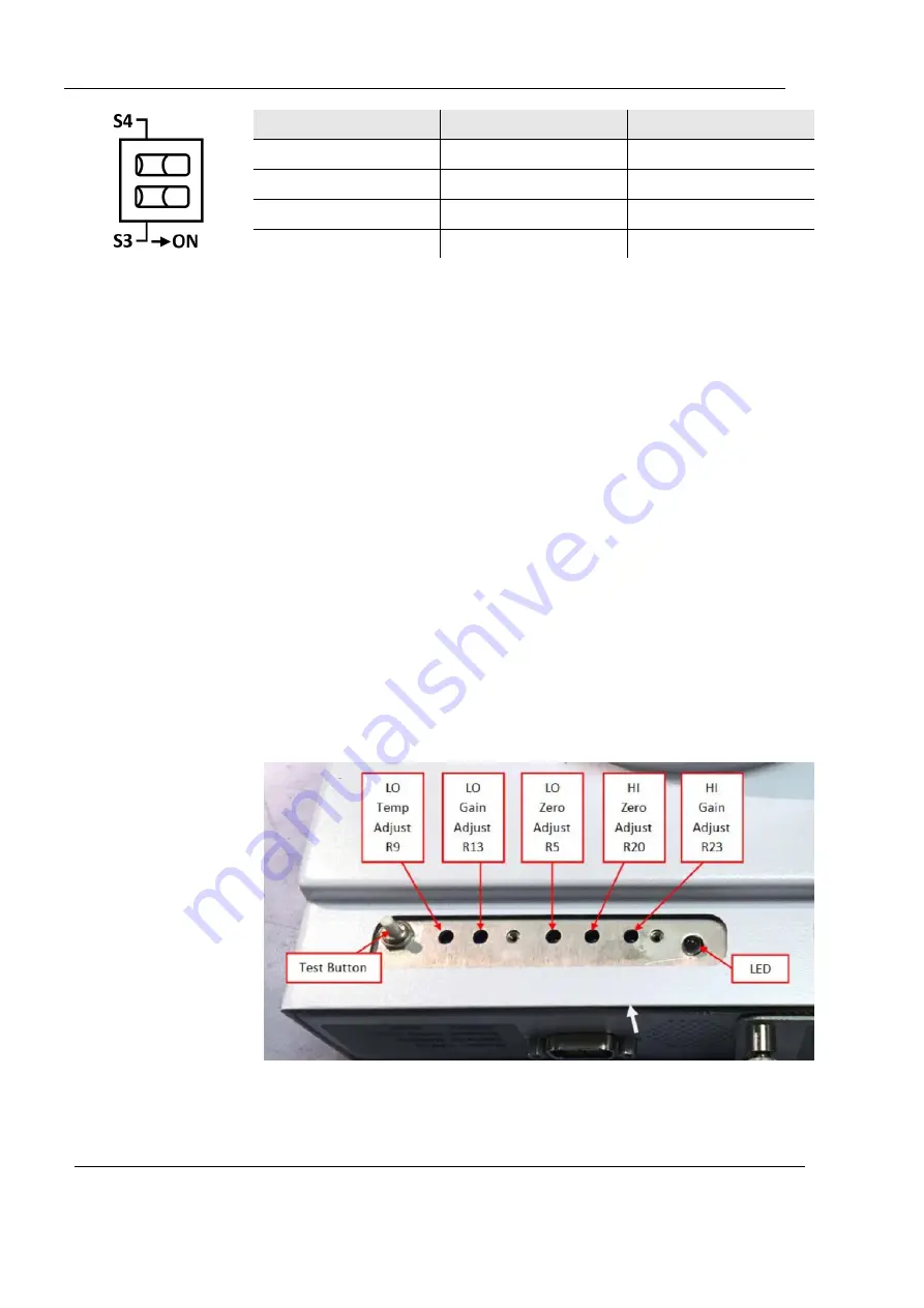
4 Operation and installation
26
SMARTS II
Alarm Threshold
S3
S4
10 %
OFF
OFF
25 %
OFF
ON
35 %
ON
OFF
50 %
ON
ON
3. Replace the battery compartment cover and finger-tighten the
four captive screws. It is important that the screws are tightened
sufficiently so that the cover slightly compresses the EMI gasket.
4.7 Zeroing procedure
It is possible to check the
Zero
setting and adjust it if necessary. The
Zero
voltage is checked by measuring the voltage between pin 2
(
ENABLE/RECORDER
) and pin 9 (
GND
) of the 9-pin D-subminiature
connector.
The battery is removed and the
BATT
–PS
switch set to
PS.
1. Connect the desired power supply
2. Remove plate adjacent to test button, with two phillips head
screws (
see 2.8
3. Adjust the middle potentiometer, R5, for 0.00 V (± 10 mV) while
monitoring the DC voltage between pin 2 and pin 9 of the 9-pin
D-subminiature connector.
This adjustment will not affect the sensitivity, as long as it is
performed correctly.
4. Reattach plate after performing adjustment.
Access to potentiometer adjustment.
Содержание L3HARRIS SMARTS II
Страница 1: ...SMARTS II Ultra Wideband RF Radiation Area Monitor Operating Manual...
Страница 36: ...36 SMARTS II 7 3 Outline drawing...
Страница 37: ...7 Specifications SMARTS II 37 7 4 Declaration of conformity...
Страница 38: ...38 SMARTS II 7 5 Declaration of origin Country of Origin Germany...


