background image

  Details of the Recording Method 


9-39 

(00400) 


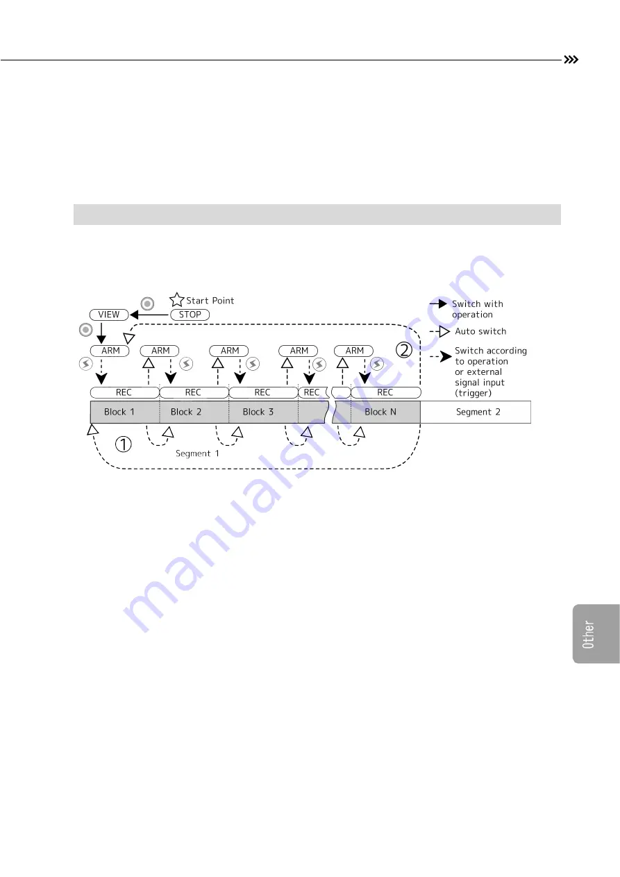
Multi trigger recording method, auto segment (block) switching: CONTINUOUS 
Example split into two segments with recording in segment 1. 


After switching to the ARM mode, input the trigger to switch to the REC mode. After completing 
recording according to the trigger timing, it automatically moves to the next block and switches to the 
ARM mode.   


After the recording of all the blocks finishes, it moves to a top block and changes to ARM mode again. 
(Overwrite recording of the top block is carried out.) The display of the frame counter in which a 
recording block is shown returns to 01. 

 
Please press the STOP key, when you end recording. The image of the block during recording is recorded to the 
timing which pressed the STOP key. 


MULTI3(C) 

Содержание ST-839

Страница 1: ...Basic Operations Live Display User s Manual 800400 0A NOV 2015 High Speed Camera System Model ST 839 Introduction Preparations Recording Playback Save System Other Spec Spec Index ...

Страница 2: ......

Страница 3: ...ly smaller sized camera with built in memory as compared to existing HX family Rugged design to seal up all electronic circuits and not to expose it to the air Superior Performance The Memrecam HX 7 is provided with HXLink software for remote operation via a computer As an option the J PAD3 Hand Held Remote Controller and Viewfinder allow the user to setup up the camera display live images on the ...

Страница 4: ...rage to USB compatible external memory media connected to the USB port on the camera unit Flexible data storage to external USB stick or Cfast cards Memory Backup The Memrecam HX 7 has a built in Memory Backup Battery function that protects against the loss of valuable data and images during unexpected loss of power to the camera for up to one hour Various External Interfaces The Memrecam HX 7 pro...

Страница 5: ...ese companies Descriptions of the HX 7 firmware Ver 1 71 and J PAD3 firmware Ver 2 90 are provided in this manual Reproduction of all or part of this manual without the express written consent from NAC Image Technology Inc is prohibited The contents of this manual may be changed without notification Copyright C 2015 NAC Image Technology Inc The copyright for this manual is owned by NAC Image Techn...

Страница 6: ...tions between the levels of bodily injury and damage occurring from improper use are described below Extreme danger that may result in death or serious injury Potential danger that may result in death or serious injury Potential danger that may result in minor injury or damage to the camera Warning Labels Descriptions are provided for the following warning labels Prohibited item Mandatory item ...

Страница 7: ...Safety Precautions 5 00400 Using the AC Adapter Only use the Memrecam HX 7 dedicated AC adapter with the Memrecam HX 7 camera Malfunction or fire may occur ...

Страница 8: ...g the AC adapter If water or foreign matter gets inside if the exterior breaks due to dropping if the camera becomes hotter than normal or if smoke odors or noises are emitted The camera becomes warmer during operation and is not considered to be a malfunction Contact your service center Using the cables Do not unplug the camera power cable with the power on Do not put foreign articles such as met...

Страница 9: ... dirty dusty or humid locations Do not subject to strong vibration or impact The AC adapter does not have vibration or impact resistance properties based on actual impact testing If subject to strong impact or vibration malfunction or injury may occur Contact your service center for use in harsh environments If there is a malfunction turn the power off and unplug the AC adapter The AC adapter does...

Страница 10: ... It is recommended that the camera be removed from the tripod prior to moving it Do not place heavy items on the camera If tipped over or dropped the exterior may be damaged which may result in bodily injury If heavy items are placed on it the exterior may be damaged causing the inside components to be damaged and malfunction Verify the ambient temperature of the location where used and stored Use...

Страница 11: ...ing check the ambient temperature of the location where used and stored Use temperature range 0 70 humidity 5 95 RH no condensation Storage temperature range 40 85 humidity 10 90 RH no condensation Make sure to ground the device Make sure to ground the AC3 pin connector If not grounded electrical shock may occur when the HX camera or GX HUB is touched Handling the AC adapter when moving or transpo...

Страница 12: ... the camera whenever possible to avoid electrical shock High Voltage Warning symbol Indicates the area of high voltage that is dangerous if touched When replacing fuses in the AC Power Adapter make sure to unplug the power cable from the outlet Do not open the cover Depending on the device some parts may generate high voltage internally so opening the cover may result in electrical shock Regular R...

Страница 13: ...This Booklet This Booklet 11 00400 About the notation in the text A Indicates the page referenced ...

Страница 14: ...e Fast Forward Quick Reverse 3 30 Jump to a Specific frame 3 31 Change the Playback Speed 3 32 Set the range for playback saving 3 33 Saving the Images 3 37 Lens Control 3 41 4 Recording Settings Items that can be Set for Recording 4 2 Select the Recording Speed 4 7 Select the Frame Size 4 9 Custom Settings for Recording Speed and Frame Size 4 12 Select the Shutter Speed 4 15 Set the Trigger Timin...

Страница 15: ...tings 8 9 Set the On Screen Display Information to Show Hide 8 10 Set the Contents of the Trigger Time Display 8 12 Set the Contents of the Frame Counter Display 8 13 Select the Standard Frame Time 8 16 Set the Image Center Mark to Show Hide 8 20 Set the Image to Show Hide on the Monitor 8 21 Sound Mute the Remote Control Operation 8 22 Auto View Function Settings 8 23 Auto Black Balance Settings ...

Страница 16: ...Table of Contents 14 00400 11 Index Index 11 2 ...

Страница 17: ...1 1 00400 1 Introduction Check the Standard Components 1 2 Optional Products Sold Separately 1 4 Exterior View and Names of Each Part 1 5 Flow of Operations 1 12 ...

Страница 18: ...ure all of them are included 1 2 00400 MEMRECAM HX 7 main unit HX 7 camera unit Simple J3 Cable Cable to connect to control PC MEMRECAM HX 7 includes the following memory configurations Memory 16 GB 32 GB Lens mount F mount C mount NM mount EF mount Make sure the model you purchased matches the contents Memory verification method A 1 8 A 8 29 ...

Страница 19: ...ink CD ROM PC Control Software CD ROM HXLink User s Manual HXLink Detailed User s Manual Electronic Manual HXLink Quick Start Guide HXLink Simple Users Guide HX 7 user s Manual basic HX 7 camera Basic Operation User s Manual HX 7 user s Manual CD ROM HX 7 camera User s Manual Electronic Manual this guide ...

Страница 20: ...cable which connects HX 7 to the HDMI cable of the view finder J3 Splitter Cable Input output cable for both HX and GX series HX 7 CTL Cable HX 7 dedicated ARM IN OUT FAULT STS OUT TRIG OUT input output cable HX 7 Carrying Case Case that holds the HX 7 unit and peripherals for safe transport This manual describes HX 7 operation using the J PAD3 Remote Controller Refer to the HXLink User s Manual f...

Страница 21: ...Names of Each Part The functions and use of each part can be found on the page listed for each item 1 5 00400 External View and Names on Main Unit 1 Exhaust vents A 2 2 2 Viewfinder shoe fitting A 2 5 3 Handle 4 LENS CTL connector A 10 34 Right Side 2 4 3 1 ...

Страница 22: ...Each Part 1 6 00400 1 Intake ports A 2 2 2 Exhaust vents A 2 2 3 Nameplate where the serial number is located 4 Factory time of shipment IP address an IP address at the time of the factory shipment is displayed Left Side 1 2 4 3 ...

Страница 23: ...Exterior View and Names of Each Part 1 7 00400 1 Lens mount A 2 3 Front and Back 1 ...

Страница 24: ...rt connector A 2 10 4 CTL connector A 9 42 5 J PAD3 connector A 2 9 6 REMOTE connectorr A 2 5 7 DC IN connector A 2 8 8 Status LED A 10 20 9 Memory size label 16GB or 32GB 10 USB 2 0 Port A 3 37 11 USB 3 0 Port A 3 37 12 CFast card slot A 3 37 13 Color camera label only color camera Rear Panel 10 11 7 8 13 1 2 3 6 5 12 4 9 ...

Страница 25: ...V button A 3 30 7 S SET button A 3 33 8 VIEW ARM button A 3 15 3 19 9 LOW LIGHT button A 5 13 10 Up down Left right arrows A 3 8 11 WAVE button A 3 7 12 DOWNLOAD button A 3 37 13 SET button A 3 8 14 MENU button A 3 8 15 TRIG button A 3 22 16 Hold switch A 3 8 17 E SET button A 3 33 18 PLAY button A 3 26 19 FWD button A 3 30 20 TRIG Direct button A 3 18 J PAD3 remote controller sold separately ...

Страница 26: ... and Names of Each Part 1 10 00400 External View of the Memrecam HX 7 AC Power Supply 1 DC connector A 2 8 2 Power switch A 2 12 3 AC connector A 2 8 4 AC cable A 2 8 5 DC cable A 2 8 AC POWER SYSTEM sold separately ...

Страница 27: ...nnector 2 Liquid crystal display A 3 2 3 Power switch A 2 12 4 Shoe fitting 5 HDMI Cable sold separately 6 Displayport HDMI Conversion Cable sold separately The appropriate image resolution of a view finder is 800x480 Viewfinder sold separately Refer to the viewfinder s manual for details 1 2 4 3 5 6 ...

Страница 28: ...input signal operation Auto pilot from the sequence file on the USB storage device 1 12 00400 This manual describes operation using the J PAD3 remote control The flow of basic recording playback and saving using this device is as shown in the following chart Please read the HXLink Users Guide for operations with the control software HXLink and operations with auto pilot ...

Страница 29: ... Preparations Camera Installation 2 2 Mounting the Lens 2 3 Adjusting the Lens Aperture 2 3 Connecting the Camera and Cables 2 5 Turning the Power ON OFF 2 12 Mount the EF mount adapter 2 16 Mount the EF lens 2 18 ...

Страница 30: ...w install away from walls If possible install in a location with good ventilation Make sure not to obstruct or cover the intake ports or exhaust vents Connecting the Memrecam HX 7 to a Tripod The Memrecam HX 7 requires two 3 8 16UNC diameter screws less than 7mm in length for mounting to a Tripod The weight of this device alone is approximately 2 7kg or 5 95lbs not including the handle and lens mo...

Страница 31: ...ile pressing the lens removal button on the mount adapter turn in the direction of the arrow It is recommended to put the mounting cap on the MEMRECAM HX 7 when a lens is not attached Avoid having dirt dust or other foreign matter adhere to the interior of the mount Depending on the image resolution a portion of the lens may have Vignetting Ex Nikon DX Nikkor lens 1 Remove the Protective Caps Remo...

Страница 32: ...sting the Aperture The method of adjusting the aperture is different based on whether or not the lens has an aperture ring If the lens has a diaphragm Ex SIGMA ASPHERICAL 24mm 1 1 8D EX DG MACRO Adjust the aperture with the diaphragm on the lens Turn the diaphragm in the CLOSE direction until it stops The diaphragm function is disabled Next turn the diaphragm on the lens to adjust the aperture If ...

Страница 33: ...n the diaphragm to adjust the aperture The aperture closes when turned in the CLOSE direction Image darkens The depth of field and focal range are increased The aperture opens when turned in the OPEN direction Image brightens The depth of field narrows The focus range narrows The mark on the diaphragm is the standard so adjust while verifying the actual image ...

Страница 34: ... signal output FAULT 1 FAULT status signal output TRIG OUT 1 TRIG OUT signal output J PAD For connecting the J PAD3 REMOTE ETHER 100 1000BASE T Ethernet TRIG2 2 External trigger input TRIG2 EST2 2 Exposure start signal input event input EST2 IRIG B 2 IRIG B time code input EPO 2 Exposure pulse output EPO PWRCNT 2 Power control signal input DC IN Power input USB 2 0 USB2 0 compatible device connect...

Страница 35: ...Connecting the Camera and Cables 2 7 00400 Diagram of Input Output Connections on the Rear Panel ...

Страница 36: ...the HX 7 Align the DC IN connector on the rear panel of the HX 7 with the red mark on the DC cable plug and insert until a clicking sound is heard When removing the DC cable from the MEMRECAM HX 7 grasp the shell of the plug and pull straight out When inserting and removing the DC and AC cables turn off the power to the AC adapter Do not open the cover on the AC adapter Dangerously high voltage is...

Страница 37: ...PAD3 cable can be left inserted into the HX 7 power or unplugged Afer HX 7 powered it could take some time that J Pad3 will be activated Connect the Viewfinder 1 Connect the Displayport HDMI Conversion Cable Connect a dedicated conversion cable for HX 7 Viewfinder to DP Displayport Connector Then conncet the conversion cable with HDMI cable The proper image resolution for the viewfinder A 1 11 is ...

Страница 38: ...080 LCD monitor Monitors with other resolutions other than those stated above and those with less than 1920 x 1080 can be used There are resolutions that cannot be set on some monitors Ex Some monitors with a panel resolution of 1920 1200 cannot be set to a resolution of 1920 1080 1 Connect the monitor cable Connect the DisplayPort connector of the monitor cable to the DP DisplayPort connector of ...

Страница 39: ...the Simple J3 Cable to the REMOTE connector Connect the Simple J3 Cable or the J3 Splitter Cable sold separately to the REMOTE connector 2 Connect the Ethernet cable to the Simple J3 cable Ethernet connector Connect the Ethernet cable to the Simple J3 cable Ethernet RJ45 connector Connect the other Ethernet cable to the Windows PC ...

Страница 40: ... The AC adapter power switch LED lights up When turning on the viewfinder after starting up the camera there may be nothing displayed in the viewfinder or the display may not be at the proper resolution 3 The Memrecam HX 7 will start up and perform a self diagnosis If the Viewfinder is connected the initial screen for the Viewfinder is displayed The system information is then displayed on the Moni...

Страница 41: ...3 A photographed image is displayed during self diagnosis If started up with the image recorded in the memory the recorded image is displayed A 3 24 In addition to the rear panel power button the Memrecam HX 7 power can also be controlled remotely from the external input output Power Control Input signal or PWRCNT A 9 57 ...

Страница 42: ...t Red Once the self diagnosis is done and startup is complete the PWR STS goes green and the CAM MODE is lit blue Startup completed STOP mode PWR STS Lit green CAM MODE Lit blue J PAD3 Startup The J PAD3 is powered when the Memrecam HX 7 is powered on There is no power switch on the J PAD3 After the Memrecam HX 7 startup is complete the J PAD3 startup will also be complete The STOP mode status scr...

Страница 43: ...the AC adapter power switch to OFF 3 Turn the Viewfinder power switch OFF Only when the viewfinder is connected The recorded images may be lost by turning off the AC adapter if the built in memory backup battery is not charged A 3 24 Before turning off the power download the recorded images to a USB storage device or computer Refer to the HXLink Users Guide for downloading to a computer or USB sto...

Страница 44: ...to the HX 7 and the AC adapter 2 Remove the screw securing the lens mount attached to the HX 7 Do not lose the screw 3 Remove the lens mount attached to the HX 7 Removing the EF mount adapter exposes the low pass filter Do not touch the surface The image quality may deteriorate if dirt adheres to the surface Additionally the filter is a part that is damaged easily Return to the retail outlet for c...

Страница 45: ...Turning the Power ON OFF 2 17 00400 6 Connect the cable to the HX 7 ...

Страница 46: ...gn mark on the lens and the mounting adapter red and turn the lens in the direction of the arrow until a clicking sound indicates it is locked 3 Switch the focus mode of the lens to AF To learn about how to handle the lens refer to the user s guide for the lens used Remove the EF lens 1 Remove the lens Turn in the direction of the arrow while pressing the lens removal button on the mounting adapte...

Страница 47: ...ding Settings 3 17 Start Recording ARM Mode 3 19 Trigger Input REC Mode 3 22 Memory Backup 3 24 Playback PLAY Mode 3 26 Repeated Playback LOOP Mode 3 28 Frame advance Fast Forward Quick Reverse 3 30 Jump to a Specific frame 3 31 Change the Playback Speed 3 32 Set the range for playback saving 3 33 Save the image 3 37 Lens Control 3 41 ...

Страница 48: ... A 8 13 Displays the current frame number or the remaining recordable frames and the marks of the frame information 5 SEG A 4 39 Displays the memory segment number currently being recorded or played back 6 Status Displays the operational mode for the camera 7 Play A 3 32 Playback speed for the video Units Frames second 8 Rec A 3 17 Displays the record or frame rate During the STOP and PLAY modes t...

Страница 49: ...Description A Trigger or event symbol yellow The currently displayed frame is the trigger or the event frame 3 26 9 22 EVENT input symbol light blue The signals input with EST2 EVENT input are frames with valid polarity 4 55 IRIG symbol Green IRIG synchronizing Red no IRIG synchronizing The IRIG signals and synchronization status are shown when set to IRIG time synchronization 4 63 Please refer th...

Страница 50: ...the scene number 12 SEGMENT Displays the segment number 13 Playback range bar There are six lines of information displayed on the LCD at one time for the bar and status of 2 13 The items and sequence displayed vary according to the operational mode of the camera Read the pages for each mode for details on the items displayed Verifying the Display Status Press the up down arrows on the J PAD3 Repea...

Страница 51: ...Screen Display 3 5 00400 There are 6 status LEDs on the rear panel of the Memrecam HX 7 camera LED Panel Display Status ...

Страница 52: ...hronized settings 3 22 Off Power OFF PWR STS Lit Green Power ON normal status no warning display 2 14 Lit Red Power ON fail status warning display 9 44 Off Power OFF MEM BACKUP Lit Green Memory backup is valid by AC adapter Charge High 3 24 Flashing Green Memory backup is valid by built in battery only Charge High Lit Orange Memory backup is valid by AC adapter Charge Medium Flashing Orange Memory...

Страница 53: ...ct button A 3 17 Changes the shutter speed TRIG Direct button A 3 18 Changes the trigger timing Recording and Playback STOP button A 3 13 Switches the operational mode to the STOP mode Return to the status display from the settings MENU VIEW ARM button A 3 15 3 19 Switches the operational mode to the VIEW mode and ARM mode TRIG button A 3 22 Trigger input to record images Jump into frame e g trigg...

Страница 54: ...value selection up down and playback speed Settings MENU MENU button A 3 9 Sets each selection by switching to the MENU Up down arrows Left right arrows A 3 9 Selects the desired setting Increases or decreases the set values SET button Sets the values or selection LOW LIGHT button A 5 13 Initiates the low light function DOWNLOAD button A 3 37 Downloads the recorded images WAVE button Using a part ...

Страница 55: ...next page all types of setting screens can be accessed from the TOP MENU During status display in the STOP mode press the DOWNLOAD button to switch to DOWNLOAD Images can be saved to USB media on the DOWNLOAD screen During status display in the STOP mode simultaneously press the STOP TRIG and SET buttons to switch to the SYSTEM SETUP MENU You can also restore the network settings or factory settin...

Страница 56: ...J PAD3 Operation 3 10 00400 ...

Страница 57: ...s shown on the first line 3 Use the up down arrows to select SYS MENU and press the SET button Use the up down arrows to the desired selection then select SYS MENU and press the SET button Press the SET button to display the SYS MENU sub menu TOP MENU SYS MENU 4 Use the up down arrows to select INFO and press the SET button Use the up down arrows to move to the selected item reverse display select...

Страница 58: ...STOP TRIG and SET buttons Simultaneously press the STOP TRIG and SET buttons The SYSTEM SETUP MENU appears Displaying the VIEW MENU 1 Access VIEW A 3 15 If in the STOP mode or ARM mode switch to the VIEW mode 2 Press the MENU button to display the VIEW MENU VIEW MENU is displayed on the first line Please refer to this book for saving images with the DOWNLOAD button A 3 37 ...

Страница 59: ...us display and then press the STOP button again The status LED for CAM MODE on the rear panel of the camera lights up in blue The images saved in the camera memory appear on the screen Information relating to the saved images and playback is displayed and the status indicates STOP mode If there are no images saved in memory the test image recorded for auto diagnosis during startup appears The on s...

Страница 60: ...ng ID Current ID Number Setting SCENE Next Scene Number to be Recorded SEGMENT Current Memory Segment Number The mark for the position of the current image display is shown on the playback range bar If no images are saved in memory the playback range bar will be empty If no images are saved in memory the TIME is displayed as Operating Panel Display The word STOP above the STOP button flashes The s...

Страница 61: ...he VIEW ARM button again The camera will automatically perform a black balance when switching to the VIEW mode A 8 25 Adjust the lens aperture and focus subject and camera settings in the VIEW mode The status LED for CAM MODE on the rear panel of the camera lights up in white The image to be recorded is displayed live in View mode The current recording settings are shown as on screen display infor...

Страница 62: ...FRAME Displays the Frame Number just before the STOP mode TIME Displays the Frame Time just before the STOP mode SEGMENT Displays current Memory Segment Number The playback range bar is not displayed If an image is not saved in the camera memory the TIME is displayed as Operating Panel Display The word VIEW above the VIEW ARM button flashes The word FRM RATE above the FRM RATE direct button flashe...

Страница 63: ...lected The frame rate can be changed from MENU Custom settings are also available Go to A 4 14 to set the frame rate from MENU Go to A 4 12 to set a custom frame rate After changing the frame rate perform a black balance A 4 23 Select the Shutter Speed Set the shutter speed exposure time according to the speed of the event to eliminate motion blur 1 Access the VIEW mode or STOP mode Switch to the ...

Страница 64: ...iming Trigger Timing Start trigger START Use a START Trigger for starting a recording immediately after trigger input Center trigger CENTER Use a Center Trigger for recording pre and post images after trigger input End trigger END Use an END Trigger for recording images after trigger input ending upon trigger input Custom trigger 000 Custom setting by user Post trigger 000000001 Use a Post Trigger...

Страница 65: ...and then select the ARM mode If the MENU is displayed press the STOP button once Select the status display and press the VIEW ARM button again The black balance is automatically acquired when selecting the ARM mode A 8 25 Camera settings cannot be changed while in the ARM mode The status LED for CAM MODE on the rear panel of the camera lights up in purple External input signals ARM command can be ...

Страница 66: ...mera recording settings cannot be changed in the ARM mode Select the STOP mode and then change the camera recording settings The noise of the image from the image sensor of the MEMRECAM HX 7 changes according to the speed This noise is called fixed pattern noise which has a different pattern from each sensor The HX 7 reduces noise by correcting the fixed pattern noise as well as noise from tempera...

Страница 67: ...de the Memrecam HX 7 continuously records images to the memory The camera records in a ring buffer first in first out writing over its memory until stopped The Memrecam HX 7 continues to record over its memory until the trigger is received Ring Buffer ...

Страница 68: ...put and the status LED for CAM MODE lights up in orange during REC mode In addition to the J PAD3 buttons you can input using the trigger Input TRIG with external trigger input signals TRIG1 TRIG2 A 4 48 Automatic trigger input after changing images during recording Image trigger A 4 29 The image being recorded is shown live The current camera settings are shown on the screen display with informat...

Страница 69: ...splays current Shutter Speed TRIGGER Displays current Trigger Timing Settings ID Displays current ID Number SCENE Displays current Scene Number PLAY Displays Playback Rate FRAME Displays Frame Number 0000 TIME SEGMENT Displays Memory Segment Number The playback range bar is not displayed Operating Panel Display The word ARM above the VIEW ARM button flashes The word TRIG above the TRIG button flas...

Страница 70: ...cording immediately before can be saved by the power supplied from the AC adapter or the internal backup battery hereafter battery even if the power to the main unit is turned OFF during recording If there is no power supplied from the AC adapter it switches to memory backup by the battery While the Memory Backup is valid a status LED of MEM BACKUP turns on or blinks as follows Lit Green Memory Ba...

Страница 71: ...ssible charging the built in battery while the power is supplied to the MEMRECAM from the AC adapter If not charged the images in memory may be lost due to over discharge of the protection circuit No Light Memory backup is invalid The MEM BACK UP LED turns off if the Memory Backup is not charged or if there are no images in the camera memory Indications of battery level are for reference purpose o...

Страница 72: ...ress the PLAY button again Or press the dial instead of the PLAY button to playback the recorded images The recorded images in memory are played back Information relating to the recorded images and playback information is displayed on screen The status is displayed as PLAY A yellow event mark is displayed on the frame counter in the trigger frame A 3 22 and the event frame A 9 22 An event mark is ...

Страница 73: ...urrent Memory Segment Number The mark for the current playback position is shown on the playback range bar This mark moves to the playback end frame and returns to the STOP mode upon completion of playback FRM RATE FRM SIZE SHUTTER and TRIGGER are the camera settings and not settings for playing back recorded images In the STOP and PLAY modes settings for checking the recorded images fast forward ...

Страница 74: ...old down the PLAY button while the STOP mode status is displayed Select to the LOOP mode from the STOP mode and repeatedly playback the playback range Directly Select to the LOOP mode without going through the PLAY mode See Playback and Save Range Settings A 3 33 for the repeat position in the LOOP mode The recorded images in memory are played back Information relating to the images recorded in th...

Страница 75: ...ER Displays the Trigger Timing ID Displays the current ID Number SCENE Displays the previously recorded Scene Number SEGMENT Displays the current Memory Segment Number The mark for the current playback position is shown on the playback range bar When this mark gets to the playback end frame it returns to the playback start frame and continue playback FRM RATE FRM SIZE SHUTTER and TRIGGER are setti...

Страница 76: ...LCD display shows the status Function Operation Description Frame advance Press the FWD button to move ahead one frame or turn the dial up Reverse Frame Press the REV button to reverse one frame or turn the dial down Fast Forward Hold Continue pressing the FWD button for fast forward Release to stop Or Press the dial and turn up Release to stop Quick Reverse Hold Continue pressing the REV button f...

Страница 77: ...iption Trigger Frame Move to the trigger frame frame with trigger input 1 Start Frame Press the TRIG and REV buttons Move to the start frame of the recorded video End Frame Press the TRIG and FWD buttons Move to the end frame of the recorded video Event Frame 2 Move to the next event frame when pressed Move to the trigger frame with the first operation 1 If there is no trigger frame in the recordi...

Страница 78: ...uring reverse playback the speed of the reverse playback decreases If slowed down past 1 during reverse playback playback is in the forward direction Press the REV button during playback or turn the dial in the direction of the arrow The playback speed decreases each time it is pressed If the playback speed is less than 1 the playback speed is negative reverse playback During reverse playback the ...

Страница 79: ... as the playback start frame If set the word S SET above the S SET button flashes Set the playback end frame Sets the current frame as the playback end frame If set the word E SET above the E SET button flashes Cancel the playback start frame Hold Cancel both Cancels the playback start frame settings The first frame for the recorded video becomes the playback start position Cancel the playback end...

Страница 80: ...back range playback start frame and playback end frame are set from the recorded frames displayed in black There is no jump function to the position of the set playback start frame or playback end frame If played back in the PLAY mode A 3 26 Playback Start Position Operation Before the playback end frame Plays back to the playback end frame and stops Switches to the STOP mode During reverse playba...

Страница 81: ... frame returns to the playback start frame and repeatedly plays back the playback range After the playback end frame Plays back to the end frame returns to the playback start frame and repeatedly plays back the playback range During reverse playback the playback start frame or first frame plays then returns to the playback end frame and repeatedly plays back the playback range ...

Страница 82: ...t frame 50 shown to the left of the Frame Playback End Frame Set Playback start frame Not set Playback end frame 1000 Current frame 50 shown to the right of the Frame Playback from Before the Playback Start Frame Playback start frame 1000 Playback end frame 1000 Current frame 2000 shown to the left of the frame shown to the right of the frame since the playback end frame is set Playback after the ...

Страница 83: ...ead the user guide with the USB device for use of the USB storage device Make sure to plug USB storage after camera powered on Do not unplug during camera powered on Make sure to plug USB storage after camera powered on Do not unplug during camera powered on Two USB ports available with HX 7 and choose appropriate one according to USB device type USB2 0 Support to USB2 0 USB3 0 Support to USB2 0 3...

Страница 84: ...al of Cfast card for more details Insert Cfast card before camera powered on and do not unplug during camera powered on Be sure to insert Cfast card with camera powered off When two or more USB devices CFast cards will be connected A 7 15 The Memrecam HX 7 uses Windows Embedded in the camera operating system Write protection is not performed in the system area for camera system protection Use caut...

Страница 85: ...e DOWNLOAD button The J PAD3 display switches to the SAVE mode The LED on the top right of the DOWNLOAD button lights up The save start frame START and the save end frame END appears The range cannot be changed here 4 Press the SET button The word SET flashes Press the SET button to start saving 5 Start saving The save file name is automatically set and shown as FILE MCFF0000 MCF The save progress...

Страница 86: ... be saved Either set a smaller save range or use a USB device with adequate space The save time varies according to the performance of the device connected Saved video files cannot be played back on the MEMRECAM HX 7 Play back the saved video file with the control software HXLink See the HXLink User s Guide for details MCFF is the video file format for MEMRECAM A 7 8 Save the video from MENU A 7 3...

Страница 87: ...ount adapter lens adjustment and focus can be controlled with a simple key stroke 3 41 00400 Menu for the EF mount adapter Does not operate other lens mount options Display LENS MODE The MENU key is pressed pressing the WAVE key The LENS MODE will appear ...

Страница 88: ...d by the highlight Direct Buttons FRM RATE direct keys Changes the recording speed SHUTTER direct keys Changes the shutter speed TRIG direct keys Changes the focus step Recording and Playback STOP key It returns from LENS MODE to a status screen display LENS MODE Inside is VIEW and ARM even if it presses the STOP key A state is continued ...

Страница 89: ...IS according to operation of the dial S SET key Changes the f stop value E SET key Changes the f stop value Dial Changes the focus f stop value Also press and turn to change the focal step Settings MENU MENU key Switches to the status screen display from the LENS MODE Up down left right keys Selects the item and changes the set values SET key Sets the settings values and items LOW LIGHT key Uses t...

Страница 90: ...Lens Control 3 44 00400 Hold switch Temporarily disables operation from the J PAD3 ...

Страница 91: ...zation dial 3 47 IRISINIT Changes the f stop value with the iris initialization dial 3 47 ZOOM Changes the focus value with the zoom dial 5 4 Items shown with a dark background are those not described in Recording Settings Press the STOP or MENU keys to return to the status screen from the LENS MODE An iris diaphragm of a lens is displayed on superposition information with F number An iris diaphra...

Страница 92: ... the HX 7 When changing lenses Turn the focus mode switch on the EF lens mount to AF Initialize again if the power to the HX 7 is cut off When the focal ring of EF mount lens is manually turned after initialization work a focus may be unable to adjust in the right range by subsequent lens control In that case please do the initialization work of a focus again ...

Страница 93: ... arrows 3 Press the SET key 3 Warning is displayed to press the SET key When initializing the SET key is pressed once again Initialize focus from the LENS MODE Initialize the focus 1 Access the LENS MODE A 3 41 4 Access the LENS MODE from the status screen 2 Select FOCUSINT with the up down arrows 3 Press the SET key 5 Press the SET key to perform focus initialization ...

Страница 94: ...y and an E SET key A 3 43 Change by the dial key Change by the up down left right arrows and set key Change by right left arrows Change by the dial key 2 Select IRIS with the up down arrows Move the selected item reverse display with the up down arrows and select either IRIS or IRISINT The figure is an example selecting IRIS 3 Adjust the iris IRIS with the dial 7 Change the f stop value and the f ...

Страница 95: ...IS with the up down left right arrows 8 Change the f stop value and the f stop value after the change is displayed in IRIS Change by right left arrows 2 Select IRIS with the up down arrows and press set 3 Adjust the iris IRIS with the left right arrows Change the f stop value and the f stop value after the change is displayed in IRIS ...

Страница 96: ...set key Change by right left arrows Change by the dial key 2 Select FOCUS with the up down arrows Move the selected item reverse display with the up down arrows and select FOCUS FOCSSTEP FOCSINIT or ZOOM The figure is an example selecting FOCUS 3 Adjust the focus step by pressing the dial while turning 10 Change the focus step and the step value after the change is displayed in FOCSSTEP Select the...

Страница 97: ...ight left arrows Adjust FOCUS by left right key New value will be indicated at FOCUS Change by right left arrows 2 Select FOCUS with the up down arrows 3 Adjust the focus with the up down right left arrows Adjust FOCUS by left right key New value will be indicated at FOCUS Focus can be controlled by HX Link Refer to HX Link operation manual for details ...

Страница 98: ...3 52 00400 ...

Страница 99: ...rame Rates 4 26 Input the Trigger with Image Trigger 4 29 Use the Auto Exposure Function 4 34 Select the Recording Bit Length 4 37 Set the Recorded Scene Number 4 38 Partitioning the Memory 4 40 Select the Recording Method 4 42 Trigger Input from an External Trigger 4 48 Synchronized Recording to the External Synchronization Signals EST 4 51 Synchronized Record Timing 4 61 PIV Particle Image Veloc...

Страница 100: ...ite balance settings during playback 6 9 ENHANCE Enhance settings during playback 6 10 GAMMA Gamma settings during playback 6 10 CHROMA Chroma settings during playback 6 11 KNEE Knee settings during playback 6 11 RGB COR RGB matrix settings during playback 6 12 LUMINANC Luminance settings during playback 6 12 LOCK PC operation lock settings 8 7 MEM SEG Segment selection 4 41 SYS MENU Jump to SYS M...

Страница 101: ...M DISP Frame number display settings 8 13 FRM TIME Frame time display settings 8 16 TIMROUND Rounding settings 8 14 REL TIME Relative time display settings 8 18 EXP TIME Exposure timing settings 4 68 SYNC TIME Synchronization time settings 4 61 SYNC SEL Synchronization signal selection settings 4 53 EST VIEW Synchronization settings for the VIEW mode during external synchronization 4 60 EST MODE E...

Страница 102: ...utter line noise correction selecting settings 8 26 WARNING Warning display settings 8 27 TRIG SET Trigger settings 4 45 4 49 SIG SET Input output signal settings 4 69 SYS SET System settings 4 40 DISP SET Monitor resolution settings 8 5 INFO System information display 8 29 Items in the table with dark backgrounds are items not described in Recording Settings Press the STOP or MENU buttons to retu...

Страница 103: ...e frame size settings 4 12 SHUTTER Shutter speed settings 4 15 DUALRATE Variable frame rate settings 4 26 AOI Photometry area settings 4 32 IMG TRIG Image trigger settings 4 29 IMGTRULE Image trigger standard luminance settings 4 31 AEC Auto exposure function settings 4 34 DRES DRES settings 4 34 LOWLIGHT Low light function settings 5 13 GXC Sensitivity extension function settings 4 34 S GAIN Sens...

Страница 104: ...ettings 5 11 LUMINANC Luminance settings 5 12 DEPTH Recording bit length settings 4 37 ZOOM Video display zoom settings 5 4 SCROLL Video display scroll 5 6 Items in the table with dark backgrounds are items not described in Recording Settings Press the STOP or MENU buttons to return to the status screen from the VIEW MENU ...

Страница 105: ...d based on the speed of the event 1 Access the VIEW MENU A 3 12 Access the VIEW MENU from the VIEW mode 2 Select the FRM RATE with the up down arrows Use the up down arrows to move to the selected frame rate and select FRM RATE 3 Select the Frame Rate Select the frame rate to be set using the left right arrows The frame size automatically changes according to the frame rate ...

Страница 106: ... 6 000 8 000 10 000 12 000 15 000 20 000 25 000 30 000 40 000 50 000 60 000 80 000 100 000 150 000 200 000 frames second The frame rates can be changed with the direct button A 3 17 See A 4 12 for record rates that are not preset The frame size that can be set for each frame rate varies A 4 10 Selectable Frame rates HX 7 ...

Страница 107: ...rizontal and vertical pixels per frame 1 Access the VIEW MENU A 3 12 Access the VIEW MENU from the VIEW mode 2 Select the FRM SIZE with the up down arrows Use the up down arrows to select the Frame Size and select FRM SIZE 3 Select the frame rate with the left right arrows Select the frame rate to be set using the left right arrows The frame size that can be set changes according to the frame rate...

Страница 108: ...0 2 000 1920 1080 1664 1248 1536 1296 1408 1408 1280 960 1280 720 2 500 1408 1184 1408 1056 1280 1280 1280 1232 1280 960 1280 720 3 000 1280 960 1280 720 1280 1072 1152 1152 1152 1120 4 000 1280 720 1152 864 1024 928 5 000 1024 768 1024 720 896 832 6 000 896 736 768 768 8 000 768 624 640 640 10 000 640 592 640 480 576 592 12 000 640 480 576 536 512 544 15 000 576 432 512 472 448 472 20 000 512 352...

Страница 109: ...Select the Frame Size 4 11 00400 Frame rate Frame Size that can be Selected 100 000 320 88 320 32 150 000 320 48 200 000 320 32 ...

Страница 110: ... down arrows to move to the selected item reverse display and select CUSTOM F Press the SET button to display the CUSTOM F sub menu 3 Select the value for priority using PRIORITY Use the up down arrows to move to the selected item reverse display and select PRIORITY Use the left right arrows to select either the frame rate or the frame size to have priority for the settings RATE Frame rate takes p...

Страница 111: ...play and select FRM SIZE Press the SET button to set the frame rate 8 Input the frame size Use the left right arrows to increase or decrease the horizontal pixels and the up down arrows to increase or decrease the vertical pixels 9 Press the SET button Press the SET button to set the frame size The frame rate can be set in units of 10 frames second The frame size can be set in units of 64 horizont...

Страница 112: ...sing the SET button to input a value higher than the upper limit for the frame size in the frame rate the maximum frame rate that can be set is set If the frame size input of a value higher than the upper limit for the frame rate increases the frame rate is automatically decreased Limitations on the frame size by the frame rate refer to the limitations on the available pixels number of horizontal ...

Страница 113: ... to move to the selected shutter speed and select SHUTTER 3 Select the shutter speed with the left right arrows Use the left right arrows to select the shutter speed or exposure time Preset Shutter Speeds HX 7 OPEN 1 100 1 250 1 500 1 1 000 1 2 000 1 5 000 1 10 000 1 20 000 1 50 000 1 100 000 1 200 000 1 333 333 1 500 000 1 1μs The upper limit for the shutter speed is determined by the frame rate ...

Страница 114: ...ter speed Use the left right arrows to move columns and increase or decrease the value with the up down arrows Values are in us micro second units 3 Press the SET button Press the SET button to set the shutter speed The upper limit for the shutter speed is determined by the frame rate If a value higher than the upper limit for the shutter speed is input the maximum value that can be set is determi...

Страница 115: ...000001 With the Start Trigger 95 of the record time from the trigger input to the end of recording can be recorded The Start Trigger is used when recording an event that starts immediately after the trigger is input With the Center Trigger half of the recording time is recorded before and after the trigger input The Center Trigger is used when recording an event that requires both pre and post ima...

Страница 116: ...n event that ends when the trigger is input With the Custom Trigger if positive numbers are set the frame numbers recorded from the start of the recording to the trigger input and the frame rate recorded from the trigger input to the end of recording can be set in 1 increments The example in the figure shows a Custom Trigger timing value of 25 End Trigger Custom Trigger ...

Страница 117: ...the point after trigger input when the same time elapses The Post Trigger also functions as a direct trigger and the frame rate in 1 frame increments can be set for the time from trigger input to the start of recording The maximum value for the frame rate is the larger of 600 seconds or 65536 frames For example if the frame rate is set to 10000 the recording starts when the amount of time equivale...

Страница 118: ...W mode 2 Select TRIGGER with the up down arrows Use the up down arrows to move to the TRIGGER type and select TRIGGER 3 Select the trigger timing with the left right arrows Use the left right arrows to select the trigger type START Start Trigger CENTER Center Trigger END End Trigger 000 Custom Trigger 000000001 Post Trigger ...

Страница 119: ...rows to select Custom Trigger and press the SET button The Custom Trigger position is 2 nd from the right and is displayed as 000 2 Input the custom trigger value Use the left right arrows to move columns and increase or decrease the value with the up down arrows Values are in 1 increments 3 Press the SET button Press the SET button to set the Custom Trigger ...

Страница 120: ...er position is displayed as 000000001 2 Input the Post Trigger value Use the left right arrows to move columns and increase or decrease the value with the up down arrows Values are in 1 frame increments 3 Press the SET button Press the SET button to set the Post Trigger Trigger timing type can be selected from the TRIG direct button A 3 18 The Custom Trigger and Post Trigger values cannot be chang...

Страница 121: ...balance the sensor when switching to the STOP VIEW and ARM modes Automatically set black balance with A 8 25 Set Black Balance Sets the black balance correction to enable or disable Also the black balance data can be captured manually 1 Access the STOP mode or the VIEW mode If in the ARM mode switch to the STOP or VIEW mode Go to VIEW mode when making Black Balance live images Go to STOP mode when...

Страница 122: ...to switch the black balance setting details OFF No black balance correction REG Black balance correction SET Black balance 5 Perform black balance Select SET and the HX 7 black balance mechanical shutter closes to obtain the black balance The setting will automatically switch to REG after retrieving the black balance ...

Страница 123: ...ot using GXC For example with the GXC function ON 2560 1920 has the same angle of view as 1280 960 when the GXC function is OFF Using the GXC Function If using the GXC function first set the frame size to 1280 x 960 or less In HX 4 the GXC function OFF is also hung horizontal 1280 and vertical 960 and is large impossible Change the frame size A 4 9 1 Access the TOP MENU A 3 11 Access the TOP MENU ...

Страница 124: ...during low speed recording can be set at a fraction of the normal recording with a setting range of 2 100 Low speed recording is performed until the trigger is input and recording is conducted at a normal speed only for the frames set after the trigger After recording the set number of frames if there is more memory further recording can be performed at a low speed until there is no more memory Th...

Страница 125: ... the variable frame rate ON Use the up down arrows to move to the selected item reverse display and select DUALRATE Select ON with the left right arrows 4 Select RATIO with the up down arrows low speed ratio and press the SET button Use the up down arrows to move to the selected item reverse display and select RATIO Press the SET button to set the low speed ratio 5 Input the low speed ratio and pr...

Страница 126: ... down arrows to move to the selected item reverse display and select BASERATE Press the SET button to set the normal frame rate 7 Input the normal frame rate and press the SET button Use the left right arrows to move columns and increase or decrease the value with the up down arrows Press the SET button to set the normal frame rate ...

Страница 127: ...ion area and standard luminance update method is specified Using the Image Trigger 1 Access the VIEW MENU A 3 12 Access the VIEW MENU from the VIEW mode 2 Select IMG TRIG with the up down arrows Use the up down arrows to move to the selected item reverse display and select IMG TRIG 3 Use the left right arrows to select the image trigger detection sensitivity Use the left right arrows to turn the s...

Страница 128: ...h HXLink If the image trigger set values are not suitable for the image an unexpected trigger is generated or a trigger is not generated in the required location Take a test photograph check the trigger and select the appropriate setting Sensitivity Setting Standards Setting Acceptable Not acceptable Do Not Use LOW Record in a location with flickering such as with fluorescent lighting Where large ...

Страница 129: ...for the image trigger luminance standard FOLLOW Automatically follow the luminance standard START Standard when starting the ARM mode MANUAL Standard when updated from the J PAD3 The following settings are available for the method of updating the luminance standard FOLLOW Generally follows the luminance standard Use if recording outdoors when the ambient brightness gradually changes in conjunction...

Страница 130: ...area of interest FULL Complete image recorded CENTER Center of the image recorded 25 of the area UPPER Top half of the image recorded LOWER Bottom half of the image recorded LEFT Left half of the image recorded RIGHT Right half of the image recorded CUSTOM Area of interest designated by HXLink The set area of interest can be used for both the auto exposure function and the image trigger function I...

Страница 131: ... will input if there are changes to the image The background of on screen display on the monitor or viewfinder screen will be blue with the Image Trigger displayed above 3 If the luminance standard update method is set to MANUAL use the VIEW ARM button to determine the luminance standard Press the ARM button to determine and update the luminance standard The luminance standard can be updated multi...

Страница 132: ...the auto exposure function The area of interest for the auto exposure function has the same settings as the image trigger area of interest AOI A 4 32 1 Access the VIEW MENU A 3 12 Access the VIEW MENU from the VIEW mode 2 Select the AEC with the up down arrows Use the up down arrows to move to the selected item reverse display and select AEC 3 Select the adjustment level for the auto exposure func...

Страница 133: ...t with SHUTTER from 10 μs This adjusted value is saved for each frame as the shutter speed for the recorded frame Cannot be used at the same time as the image trigger function A 4 29 When the DRES A 4 29 is used please turn OFF a function If the AEC is used there is restriction of a recording rate to effective pixels Example HX 7 At the time of 1920x1080 Recording rate which can be selected preset...

Страница 134: ...up down arrows to move to the selected item reverse display and select AEC 3 Select the adjustment level for the DRES with the left right arrows Use the left right arrows to turn DRES ON OFF and to select the adjustment level OFF A dynamic range is set up to about 200 It is the normal setting LOW A dynamic range is set up to about 400 MID A dynamic range is set up to about 800 HIGH A dynamic range...

Страница 135: ...nt of recording time available 4 37 00400 Set the Recording Bit Length Select the bit length from the three choices of 12bit 10bit or 8bit 1 Access the VIEW MENU A 3 12 Access the VIEW MENU from the VIEW mode 2 Select the DEPTH with the up down arrows Use the up down arrows to move to the selected item reverse display and select DEPTH 3 Select the recording bit length with the left right arrows Se...

Страница 136: ...ue for the Recorded Scene Number Sets the initial value for the recorded scene number You can start the scene numbers from any number such as when correcting the scene number for a new recording or when setting a continuation number from a different recording 1 Access the VIEW MENU A 3 12 Access the VIEW MENU from the VIEW mode 2 Select the SCENE with the up down arrows and press the SET button Us...

Страница 137: ...nts and recording Immediately start recording after recording without waiting the time for saving Batch download with HXLink after recording multiple scenes Save only the necessary scenes to a USB CFast after recording multiple scenes Can set and get the black balance in each segment Read the HXLink users guide for the method of setting custom segments Videos recorded to the memory are all erased ...

Страница 138: ...use the left right arrows to select the number of segments 3 Press the SET button Press the SET button to display a confirmation message asking if it is acceptable to erase the video made with the memory partition settings 4 Press the SET button again If there are no problems with erasing the saved video press the SET button again and the memory will be partitioned into segments If the segments ar...

Страница 139: ...SEG A 3 11 Access TOP MENU MEM SEG from the STOP mode 2 Select the segment with the up down arrows and press the SET button Use the up down arrows to select the memory segments to play back Press the SET button to set the segment selection Segments where recording has been completed will show the scene number and recorded date time in the four columns on the right side Segments that haven t been r...

Страница 140: ...the normal recording method but the external input output trigger signals for the second and subsequent times are considered an event Burst Recording Method Method of recording only the frames for the time frame enabled by the external input output trigger to the memory Multi Trigger Recording Method Method of recording multiple events by partitioning a single segment into a maximum of 16 equally ...

Страница 141: ...eted are not protected Once recording of all segments is complete it returns to the top segment and continues recording in the ARM mode Press the STOP button to finish recording Auto Block Switching Only for the multi trigger recording method ALL BLOCKS Automatically switches blocks when recording is done Once the block is switched it automatically switches to the ARM mode Segments are not automat...

Страница 142: ...L Normal LOOP EVENT Event No EVENT A Event AUTO EVENT L Event LOOP BURST Burst No BURST A Burst AUTO BURST L Burst LOOP MULTI A Multi trigger ALL BLOCKS MULTI C Multi trigger CONTINUOUS MULTIS A Multi trigger AUTO MULTIS L Multi trigger LOOP MULTI1 A Multi manual ALL BLOCKS MULTI1 C Multi manual CONTINUOUS MULTI2 A Multi manual ALL BLOCKS MULTI2 C Multi manual CONTINUOUS MULTI3 A Multi manual ALL ...

Страница 143: ...rows to move to the selected item reverse display and select REC MODE 3 Select the recording method with the left right arrows Use the left right arrows to select the recording method to use NORMAL EVENT BURST MULTI A MULTIS L MULTI2 A MULTI3 C NORMAL A EVENT A BURST A MULTI C MULTI1 A MULTI2 C LINEAR NORMAL L EVENT L BURST L MULTIS A MULTI1 C MULTI3 A Read Details on the Recording Method A 9 14 f...

Страница 144: ...Select BLOCKS with the up down arrows and press the SET button Use the up down arrows to move to the selected item reverse display and select REC MODE 3 Input the number of blocks Use the left right arrows to move columns and increase or decrease the value with the up down arrows The minimum value is 2 and the maximum is 16 4 Press the SET button Press the SET button to set the number of blocks Re...

Страница 145: ...sed is selected Select REC MODE with the up down arrows MULTI2 A is selected as an example 3 Select BEFORMFRM with the up down arrows and press the SET button Use the up down arrows to move to the selected item reverse display and select BEFORFRM Press the SET button 4 Input the number of blocks Use the left right arrows to move columns and increase or decrease the value with the up down arrows 4 ...

Страница 146: ...ns A 10 29 The voltage tolerance is 0 5 5 5Vdc 1 Connect the BNC cable to the TRIG connector Connect the BNC cable to the TRIG connector on the rear panel Connect the other end of the BNC cable to the trigger signal output device The specifications for the external trigger signals from the TRIG2 connector are current loop input with a photo capacitor The trigger is enabled at an applied voltage of...

Страница 147: ...he External Trigger Signals 1 Display TRIG SET A 3 11 Access TOP MENU SYS MENU TRIG SET from the STOP mode 2 Select TRIG SEL with the up down arrows Use the up down arrows to select TRIG SEL 3 Select the external trigger signals with the left right arrows Select the external trigger signals with the left right arrows TRIG1 External trigger signals from TRIG connector enabled TRIG2 External trigger...

Страница 148: ...2 for external trigger filter settings With the initial settings the trigger input polarity is NEGA L for TRIG1 and CRNT ON Current ON for TRIG2 The polarity settings can be changed Select the external input output signal polarity A 4 69 If there is trigger input polarity when switching to the VIEW or ARM modes there will be a warning message indicating Warning Trigger signal is asserted on the sc...

Страница 149: ...tion signals INT Synchronizes with synchronization signals VD signals created in the HX 7 camera External synchronization signals EST2 Synchronizes with exposure start signals EST External Shutter Trigger Exposure Start input from the EST1 or the EST2 connector If recording using EST when the input signal shifts from H to L in the ARM or REC mode exposure starts and a single image is recorded The ...

Страница 150: ...er line may be shown on the image horizontal line or the image luminance may not be normal EST signal synchronization Hz maximum frame rate for the frame size in the settings frames sec 2 Example of an incorrect image EST signal input of 16 000Hz at a frame size of 384 288 For the frame rate setting select a speed close to the frequency of the input EST signal Also if there is nothing present that...

Страница 151: ...SEL 3 Select the synchronization signals with the left right arrows Select the synchronization signals with the left right arrows INT Synchronize the synchronization signals generated by the camera EST1 Not use EST2 Synchronize the external synchronization signals input from the REMOTE connector EST2 The filter setting of an external synchronization signal should read an EST filter is set up A 4 7...

Страница 152: ...comes one clock and enables highly precise synchronous photography When the cycle of an EST signal is twice less than the reciprocal of a recording rate a horizontal reinforcement like noise may appear The exposure timing at the time of A EST selecting EXP TME operates as GXnative If a frame straddling function is used even if it has selected EST MODE as EST it will become A EST setting A 4 66 1 A...

Страница 153: ...ifications A 9 49 EST2 input REMOTE connector specifications A 10 27 1 Connect the J3 split cable to the REMOTE connector Connect the J3 split cable sold separately to the REMOTE connector 2 Connect the BNC cable male to the J3 split cable EST2 EVENT input Connect the BNC cable to the J3 split cable EST2 EVENT input Connect the other end of the BNC cable to the exposure start signal output device ...

Страница 154: ...s recorded to the frame and Event input mark is displayed during playback Event signal recording is performed automatically and the settings cannot be switched to enable disable the function Operation is not related to the synchronization settings The event signal polarity utilizes EST2 polarity settings Select the polarity for the external input output signals A 4 69 EST2 EVENT Event Signal Recor...

Страница 155: ...sensor electronic shutter is OPEN it will not record properly If the exposure start signal H L is input to EST with this irregular timing the image photographed may be corrupt The exposure start signal for this irregular timing can be disabled This setting is in effect at A SET only A 4 54 The camera always runs as OFF when at synch mode of EST External Synchronization Signals with Irregular Timin...

Страница 156: ...h the up down arrows Use the up down arrows to move to the selected item reverse display and select EST SAFE 3 Turn ON with the left right arrows Use the left right arrows to select enable disable synchronization signals with irregular timing OFF Enable synchronization of synchronization signals with irregular timing the photographed image may be corrupt ON Disable synchronization of synchronizati...

Страница 157: ...settings EST1 and EST2 the background of the on screen display in the VIEW or ARM mode will be blue The notation of the frame rate will be EST1 or EST2 3 Input the trigger to finish recording Input the trigger button or external trigger and switch to the REC mode to finish recording The initial setting for the polarity when the exposure starts with EST the shutter will be OPEN is L The polarity se...

Страница 158: ...ettings only for the VIEW mode If recording with external synchronization signals EST2 set to either ON or OFF in the ARM mode to perform synchronized recording to the EST signals Also if recording with internal synchronization signals INT display and recording can be conducted for all of the internal synchronization signals regardless of the settings in EST VIEW 1 Access the SYS MENU A 3 11 Acces...

Страница 159: ...s done with the PC timing If not connected to a control PC recording with multiple cameras is synchronized but the exact time day hour minute second is not available IRIG time synchronization Time synchronized with the IRIG B timer code Select if the following occurs If using only the MEMRECAM HX 7 and inputting the IRIG B timer code from the J3 common cable sold separately IRIG B input connected ...

Страница 160: ...ith the up down arrows Use the up down arrows to move to the selected item reverse display and select SYNC TIME 3 Use the left right arrows to select the time synchronization Use the left right arrows to select the time synchronization to use ASYNC Camera time synchronization GX HUB GX HUB time synchronization IRIG IRIG time synchronization RESET Trigger RESET If using a multi camera connection wi...

Страница 161: ...IRIG B signal output device to output IRIG B signals 3 Select IRIG with the time synchronization selection Select IRIB time synchronization from the J PAD3 A 4 62 Check the VIEW screen to check if the IRIG B timer codes and time synchronization were obtained If synchronized with the IRIG B timer code An I is displayed in black letters with a green background in the superimposed frame counter If no...

Страница 162: ...t trigger reset from the J PAD3 A 4 62 Input the trigger input signals to re synchronize and start the new exposure In the figure the trigger is input during the exposure time and a new exposure starts from there Input of the trigger while importing displays the null data since there is no data after the trigger so the image is only saved as a normal image for part of the time Additionally the ima...

Страница 163: ... 2nd frame The timing to switch from the 1 st frame to the 2 nd frame is adjusted by changing the exposure time of the 1 st frame using the shutter speed settings The exposure time of the 2 nd frame is automatically determined by the frame size and cannot be changed The exposure pulse signal EPO output can be checked for the time of exposure Select either internal synchronization or EST synchroniz...

Страница 164: ...ng The following limitations apply when using the frame straddling function The restrictions regarding relationship between the frame rate and the frame size and the restrictions of exposure time are different from the normal mode frame straddling is OFF With external synchronization the EST signal exposure start signal cycle 3 frame rate The frame rate is the speed of magnitudes of 20 greater tha...

Страница 165: ...YS MENU STRADDL from the STOP mode 2 Select PREVIEW with the up down arrows Use the up down arrows to move to the selected item reverse display and select PREVIEW 3 Use the left right arrows to select the display frame Use the left right arrows to select the live display frame when frame straddling recording ANY Live display of the newest image regardless of the distinction between 1 st and 2 nd f...

Страница 166: ...e the up down arrows to move to the selected item reverse display and select EXP TIME 3 Use the left right arrows to select the exposure timing Use the left right arrows to select the exposure timing GXnative Start exposure when the exposure start signals begin K3compat Exposure ends when the recording synchronization signals start if synchronized recording with cameras other than fx K4 or K5 K4co...

Страница 167: ...G1 TRIG2 External synchronization signal input EST2 Exposure pulse output EPO ARM Command input ARM CMD ARM status output ARM STS FAULT status output FAULT 1 Access SIG SET A 3 11 Access TOP MENU SYS MENU SIG SET from the STOP mode 2 Select the external input output to be set with the up down arrows and select the polarity with the left right arrows Use the up down arrows to move to the selected i...

Страница 168: ...EGA Not available with HX 7 EST2 POSI Detects the EST signals from the EST2 input REMOTE connector at the leading edge NEGA Detects the EST signals from the EST2 input REMOTE connector at the trailing edge EPO EPO REMOTE Connecter POSI Outputs H level signals during exposure NEGA Outputs L level signals during exposure ARM CMD POSI Detects ARM command signals at the leading edge NEGA Detects ARM c...

Страница 169: ...Select the External Input Output Signal Polarity 4 71 00400 EST1 FLT Not available with HX 7 EST2 FLT EST2 filter setting SAME TRIGEDGE Trigger signal detection method OFF refer to the factory settings ...

Страница 170: ...e STOP mode 2 Select TRIG1FLT or TRIG2FLT with the up down arrows and press the SET button Use the up down arrows to move to the selected item reverse display and select TRIG1FLT TRIG1 input filter value or TRIG2FLT TRIG2 input filter value If using TRIG2FLT select SAME to set the same value as TRIG1FLT Press the right arrow to select the number to input and then press the SET button to input 3 In...

Страница 171: ...MENU SIG SET from the STOP mode 2 Select EST2 FLT with the up down arrows and press the SET button Use the up down arrows to move to the selected item reverse display and select or EST2 FLT EST2 input filter value If using EST2 FLT select SAME to set the same value as EST1 FLT Press the right arrow to select the number to input and then press the SET button to input 3 Input the EST filter value Us...

Страница 172: ...xt block but there may be times when you do not get the expected result In that case set the Trigger Signal Detection Method to edge 1 Access SIG SET A 3 11 Access TOP MENU SYS MENU SIG SET from the STOP mode 2 Select TRIGEDGE with the up down arrows Use the up down arrows to move to the selected item reverse display and select TRIGEDGE 3 Use the left right arrows to select the exposure timing for...

Страница 173: ...00400 5 Live Image Settings Items that Can be Set for the Live Display 5 2 Zoom the Live Image 5 4 Scroll the Live Image 5 6 Adjust the Image Quality of the Live Image 5 7 Using the Low Light Function 5 13 ...

Страница 174: ... 4 17 FRM RATE Frame rate settings 4 7 FRM SIZE Frame size settings 4 9 CUSTOM F Custom frame rate frame size settings 4 12 SHUTTER Shutter speed settings 4 15 DUALRATE Variable frame rate settings 4 26 AOI Photometry area settings 4 32 IMG TRIG Image trigger settings 4 29 IMGTRULE Image trigger standard luminance settings 4 31 AEC Auto exposure function settings 4 34 DRES DRES settings 4 36 LOWLI...

Страница 175: ...m settings 5 4 SCROLL Video display scroll 5 6 Items in the table with dark backgrounds are items not described in Live Display Settings Press the STOP or MENU buttons to return to the status screen from the VIEW MENU D GAIN WHT BAL ENHANCE GAMMA CHROMA KNEE RGB COR and LUMINANC are settings relating to image quality and are reflected on the recorded video after recording or on the saved video Set...

Страница 176: ...wn arrows to move to the selected item reverse display and select ZOOM 3 Select the zoom with the left right arrows Select the zoom magnification to be set with the left right arrows FIT1 Display the entire screen in the display area FIT2 Reduce and display the entire screen in about 80 of the display area if displaying the entire image on a standard NTSC monitor 1 4 Reduce the image to for displa...

Страница 177: ...ording to the settings for the connected monitor and monitor display resolution Change the display resolution on the monitor A 8 5 If the display size is larger than the display area the part off the screen can be displayed by scrolling A 5 6 Even if the image extends past the display area on the monitor when zoomed the part not displayed can be recorded ...

Страница 178: ...to move to the selected item reverse display select SCROLL and press the SET button 3 Use the up down and left right arrows to scroll Use the left right arrows to shift the display position in the horizontal direction The numbers to the left will increase or decrease Use the up down arrows to shift the display position in the vertical direction The numbers to the right will increase or decrease Pr...

Страница 179: ...age White balance Corrects the color to reflect the white properly according to various light sources Enhance Adjust the emphasis of the contour Gamma Adjusts the gradation properties darkness and brightness of the display Chroma Adjusts the saturation color concentration Knee Lowers the gain in bright areas and expands the dynamic range RGB Matrix Improves the color reproduction Luminance Propert...

Страница 180: ...nce value by recording white objects such as paper 1 Access the VIEW MENU A 3 12 Access the VIEW MENU from the VIEW mode 2 Select WHT BAL with the up down arrows Use the up down arrows to move to the selected item reverse display and select WHT BAL 3 Select the white balance with the left right arrows Select the white balance to be set with the left right arrows AUTO Auto white balance 3100K When ...

Страница 181: ...source to an appropriate level of brightness 2 Record the white objects and select the white balance settings in SET Photograph white objects to calculate the white balance data Once the white balance calculations are finished they will automatically be set as REG Set Enhance 1 Access the VIEW MENU A 3 12 Access the VIEW MENU from the VIEW mode 2 Select ENHANCE with the up down arrows Use the up d...

Страница 182: ...h the left right arrows OFF No gamma correction LOW Low gamma correction NORMAL Normal gamma correction Set the Chroma Saturation 1 Access the VIEW MENU A 3 12 Access the VIEW MENU from the VIEW mode 2 Select CHROMA with the up down arrows Use the up down arrows to move to the selected item reverse display and select CHROMA 3 Select the chroma with the left right arrows Select the chroma to be set...

Страница 183: ...t right arrows Select enable disable with the left right arrows OFF No knee correction ON Knee correction Set the RGB Matrix 1 Access the VIEW MENU A 3 12 Access the VIEW MENU from the VIEW mode 2 Select RGB COR with the up down arrows Use the up down arrows to move to the selected item reverse display and select RGB COR 3 Select the RGB matrix with the left right arrows Select enable disable the ...

Страница 184: ...ect the luminance properties to be set with the left right arrows NORMAL Display using gain gamma and knee settings normal settings LINEAR Display without any image data correction gain gamma and knee correction not used TABLE Applies the luminance properties file for individual users Can be selected CUSTOM Custom settings for luminance properties Luminance properties for TABLE and CUSTOM can be s...

Страница 185: ...T button in the VIEW mode Press the LOW LIGHT button during a live display in the VIEW mode to enable the low light function If the low light function is enabled the camera mode display indicates LLIGHT Press the LOW LIGHT button again to cancel the low light function and return to the normal display When the low light function is enabled the live display is shown at full size 2560 1920 regardless...

Страница 186: ...ight frame rate to be set with the left right arrows 100 Live image display during exposure time of 1 100 second frame rate of 100 frames second corresponding to an OPEN shutter 250 Live image display during exposure time of 1 250 second frame rate of 250 frames second corresponding to an OPEN shutter 500 Live image display during exposure time of 1 500 second frame rate of 500 frames second corre...

Страница 187: ... Select pps with the left right arrows and press the SET button to set a custom value 2 Input the low light custom exposure time Use the left right arrows to move columns and increase or decrease the value with the up down arrows The exposure time will correspond to the OPEN shutter at the input frame rate 3 Press the SET button The custom exposure time is enabled ...

Страница 188: ...5 16 00400 ...

Страница 189: ...6 Playback Settings Items that Can be Set for Playback 6 2 Zoom the Playback Image 6 5 Scroll the Playback Image 6 6 Adjust the Image Quality of the Playback Image 6 7 Select the Memory Segment for Playback 6 13 ...

Страница 190: ... settings during playback 6 9 ENHANCE Enhance settings during playback 6 10 GAMMA Gamma settings during playback 6 10 CHROMA Chroma settings during playback 6 11 KNEE Knee settings during playback 6 11 RGB COR RGB matrix settings during playback 6 12 LUMINANC Luminance settings during playback 6 12 LOCK PC operation lock settings 8 7 MEM SEG MEM SEG settings 4 41 SYS MENU Jump to SYS MENU System M...

Страница 191: ...number display settings 8 13 FRM TIME Frame time display settings 8 16 TIMROUND Rounding settings 8 14 REL TIME Relative time display settings 8 18 EXP TIME Exposure timing settings 4 68 SYNC TIME Synchronization time settings 4 61 SYNC SEL Synchronization signal selection settings 4 53 EST VIEW Synchronization settings for the VIEW mode during external synchronization 4 60 EST MODE External synch...

Страница 192: ...o black balance settings 8 25 SHLNC Shutter line noise correction selecting settings 8 26 WARNING Warning display settings 8 27 TRIG SET Trigger settings 4 45 4 49 SIG SET Input output signal settings 4 69 SYS SET System settings 4 40 DISP SET Monitor settings 8 5 INFO Information display 8 29 Items in the table with dark backgrounds are items not described in Playback Settings Press the STOP or M...

Страница 193: ...entire screen in the display area FIT2 Reduce and display the entire screen in about 80 of the display area or if displaying the entire image on a standard NTSC monitor 1 4 Reduce the image to for display 1 2 Reduce the image to for display X1 Display the image actual size X2 Double the image size for display X4 Quadruple the image size for display The zoom can be changed even when displaying live...

Страница 194: ...L with the up down arrows and press SET Use the up down arrows to select SCROLL and press the SET button 3 Use the up down and left right arrows to scroll Use the left right arrows to shift the display position in the horizontal direction The numbers to the left will increase or decrease Use the up down arrows to shift the display position in the vertically The numbers to the right will increase o...

Страница 195: ...to reflect the white properly according to various light sources Enhance Adjust the emphasis of the contour Gamma Adjusts the gradation properties darkness and brightness of the display Chroma Adjusts the saturation color concentration Knee Lowers the gain in bright areas and expands the dynamic range RGB Matrix Improves the color reproduction Luminance Properties Sets the input output properties ...

Страница 196: ...ct D GAIN with the up down arrows Use the up down arrows to move to the selected item reverse display and select D GAIN 3 Select the digital gain with the left right arrows Select the digital gain to be set with the left right arrows LOW Sensitivity one step less than NORMAL NORMAL Normal sensitivity setting HIGH Sensitivity one step higher than NORMAL ...

Страница 197: ...ng while in the VIEW mode 1 Access the TOP MENU A 3 11 Access the TOP MENU from the STOP mode 2 Select WHT BAL with the up down arrows Use the up down arrows to move to the selected item reverse display and select WHT BAL 3 Select the white balance with the left right arrows Select the white balance to be set with the left right arrows AUTO Auto white balance 3100K When the color temperature of th...

Страница 198: ...nce and set with the left right arrows OFF Do not emphasize contours LOW Low contour emphasis NORMAL Normal contour emphasis HIGH High contour emphasis Set the Gamma 1 Access the TOP MENU A 3 11 Display TOP MENU from the STOP mode 2 Select GAMMA with the up down arrows Use the up down arrows to move to the selected item reverse display and select GAMMA 3 Select GAMMA with the left right arrows Sel...

Страница 199: ... right arrows Select the chroma to be set with the left right arrows 0 0 saturation B W image 50 50 saturation 100 100 saturation normal 150 150 saturation 200 200 saturation Set the Knee 1 Access the TOP MENU A 3 11 Access the TOP MENU from the STOP mode 2 Select KNEE with the up down arrows Use the up down arrows to move to the selected item reverse display and select KNEE 3 Select the KNEE with...

Страница 200: ... LUMINANC with the up down arrows Use the up down arrows to move to the selected item reverse display and select LUMINANC 3 Select the luminance properties with the left right arrows Select the luminance properties to be set with the left right arrows NORMAL Display using gain gamma and knee settings normal settings LINEAR Display without any image data correction gain gamma and knee correction no...

Страница 201: ... Access TOP MENU MEM SEG from the STOP mode 2 Select the segment with the up down arrows and press SET Select the memory segment for playback with the up down arrows Press the SET button to set the selected segment The four digit scene number and recorded date time is displayed on the right side for the segments for which recording has been completed Segments not recorded will display on the right...

Страница 202: ...6 14 00400 ...

Страница 203: ...7 1 00400 7 Save Settings Items that can be Set for Saving 7 2 Saving Video Files 7 3 Saving Still Image Files 7 14 Selecting the USB CFast Media for Storage 7 15 Formatting USB CFast Media 7 16 ...

Страница 204: ...to USB CFast media 7 3 FREE FRM Display the number of frames that can be recorded on the USB CFast 7 5 SAVE FRM Settings for the save range on the USB CFast media 7 5 REC FRM Display the recording frame range 7 5 FILETYPE Settings for the file format on the USB CFast media 7 8 AVI SET AVI MJPEG compression ratio and playback speed settings 7 6 YC TIFF Save image display in the YC TIFF format 7 14 ...

Страница 205: ...ything including the image data obtained from the sensor the time stamp data recorded at the same time such as the time and image quality settings After saving this is optimal if making image quality adjustments with HXLink or if you need to set or record during recording The file name is MCFF sequential and the file extension is MCF AVI With an uncompressed AVI Windows standard video file format ...

Страница 206: ...of the MCFF to be saved on USB is greater than 4GB the MCFF will be split into multiple files for saving At this point the second and subsequent files saved will have V2 V3 automatically added to the end of the standard file name 1st file name MCFF0000 MCF 2 nd file name MCFF0000 V2 MCF If saving to USB media formatted with the exFAT or NTFS file system they are not divided and are saved as a sing...

Страница 207: ...ith the up down arrows and press the SET button Press the SET button to input the save range 3 Input the save range Use the left right arrows to move columns and increase or decrease the value with the up down arrows The start frame is on the left side and the end frame is on the right side 4 Press the SET button Sets the save range Displays the save range set FREE FRM It is the number of frames w...

Страница 208: ...the up down arrows and press the SET button Use the up down arrows to move to the selected item reverse display and select AVI SET Press the SET button to display the AVI SET sub menu 3 Frame rate Select PLAYRATE with the up down arrows and press the SET button Press the SET button to input the playback speed 4 Input the playback speed Use the left right arrows to move columns and increase or decr...

Страница 209: ...ty Use the left right arrows to move columns and increase or decrease the value with the up down arrows The minimum value is 1 and the maximum is 100 Image quality improves as the value increases but the file size also increases The file size decreases as the value decreases but the image quality deteriorates 8 Press the SET button Sets the compression quality Displays the compression quality set ...

Страница 210: ... press the SET button to display the USB save screen The save range is displayed on the USB save screen and SET in the 4 th row to the right of SAVE flashes 5 Press the SET button Press the SET button to start saving to the USB media After starting to save the file name is displayed in FILE The progress bar for the status of the save is displayed at the bottom of the screen 6 Press the SET button ...

Страница 211: ...TOP mode A 6 7 Open a file with HXLink to read the saved image quality settings The MCFF image quality settings can be changed without deterioration during playback using HXLink Refer to the HXLink user guide for details MCFF files can be saved from the DOWNLOAD button A 3 37 MCFF Image Quality Settings ...

Страница 212: ...left right arrows to select AVI as the file format 4 Set the frame rate A 7 6 5 Select DOWNLOAD with the up down arrows and press the SET button After selecting DOWNLOAD press the SET button to display the USB save screen The save range is displayed on the USB save screen and SET in the 4 th row to the right of SAVE flashes 6 Press the SET button Press the SET button to start saving to the USB med...

Страница 213: ... Press the SET button to end saving and return to the SAVE MENU Press the STOP button to stop saving The save will be interrupted and it will return to the SAVE MENU The MCFF image quality settings are the contents saved in the video file adjusted in the STOP mode A 6 7 The image quality settings cannot be changed after saving AVI Image Quality Settings ...

Страница 214: ...o select MJPEG as the file format 4 Set the frame rate and the compression quality A 7 6 5 Select DOWNLOAD with the up down arrows and press the SET button After selecting DOWNLOAD press the SET button to display the USB save screen The save range is displayed on the USB save screen and SET in the 4 th row to the right of SAVE flashes 6 Press the SET button Press the SET button to start saving to ...

Страница 215: ... Press the SET button to end saving and return to the SAVE MENU Press the STOP button to stop saving The save will be interrupted and it will return to the SAVE MENU The AVI image quality settings are the details saved in the video file adjusted in the STOP mode A 6 7 The image quality settings cannot be changed after saving MJPEG Image Quality Settings ...

Страница 216: ...play the file name and save the YC TIFF file Saving as YC TIFF saves the same image displayed on the monitor or viewfinder In addition to the image quality settings from the STOP mode A 6 7 it is saved as displayed with zoom A 6 5 or scroll A 6 6 However information on the on screen display is not saved The pixel size of the YC TIFF file is the size displayed on the monitor or viewfinder YC TIFF f...

Страница 217: ...E MENU A 3 11 Access TOP MENU SAVE MENU from the STOP mode 2 Select USB SEL with the up down arrows and press the SET button Use the up down arrows to move to the selected item reverse display and select USB SEL Press the SET button to display the USB SEL sub menu 3 Select the USB CFast media to use with the up down arrows and press the SET button The volume and the total capacity for the USB CFas...

Страница 218: ...1 Access TOP MENU SAVE MENU from the STOP mode 2 Select USB INIT with the up down arrows and press the SET button Use the up down arrows to move to the selected item reverse display and select USB INIT Press the SET button to display the USB INIT sub menu 3 Select LABELSET with the up down arrows and select the volume with the left right arrows Use the up down arrows to select LABELSET and select ...

Страница 219: ...the SET button to display the format screen 6 Press the SET button to start formatting A verification message is displayed to confirm formatting Press the SET button to start formatting 7 Finish formatting A message is displayed upon completion of formatting Press the SET button to switch from the format screen to the SAVE MENU or the status display ...

Страница 220: ...7 18 00400 ...

Страница 221: ...et the Contents of the Trigger Time Display 8 12 Set the Contents of the Frame Counter Display 8 13 Select the Standard Frame Time 8 16 Set the Image Center Mark to Show Hide 8 20 Set the Image to Show Hide on the Monitor 8 21 Sound Mute the Remote Control Operation 8 22 Auto View Function Settings 8 23 Auto Black Balance Settings 8 25 Set the Warning Messages to Show Hide 8 27 Display System Info...

Страница 222: ... during playback 6 9 ENHANCE Enhance settings during playback 6 10 GAMMA Gamma settings during playback 6 10 CHROMA Chroma settings during playback 6 11 KNEE Knee settings during playback 6 11 RGB COR RGB matrix settings during playback 6 12 LUMINANC Luminance settings during playback 6 12 LOCK PC operation lock settings 8 7 MEM SEG Segment selection 4 41 SYS MENU Jump to SYS MENU System Menu SAVE...

Страница 223: ...8 16 TIMROUND Rounding settings 8 14 REL TIME Relative time display settings 8 18 EXP TIME Exposure timing settings 4 68 SYNC TIME Synchronization time settings 4 61 SYNC SEL Synchronization signal selection settings 4 53 EST VIEW Synchronization settings for the VIEW mode during external synchronization 4 60 EST MODE External synchronization accuracy setting 4 54 EST SAFE Settings to ignore irreg...

Страница 224: ...n selecting settings 8 26 WARNING Warning display settings 8 27 TRIG SET Trigger settings 4 45 4 49 SIG SET Input output signal settings 4 69 SYS SET System settings 4 40 DISP SET Monitor resolution settings 8 5 INFO System information display 8 29 Items in the table with dark backgrounds are items not described in System Settings Press the STOP or MENU buttons to return to the status screen from ...

Страница 225: ... Access DISP SET A 3 11 Access TOP MENU SYS MENU DISP SET from the STOP mode 2 Select the display resolution with the up down arrows and press the SET button Use the up down arrows to move to the selected item reverse display and select the display resolution and refresh rate Information not shown can be displayed by moving the left right arrows The reverse display on the right side is the current...

Страница 226: ...00 4 After rebooting the screen display resolution will switch After rebooting the monitor display will switch to the display resolution set The display resolutions and refresh rates shown in the list vary according to the monitor connected ...

Страница 227: ...nt accidental operations from HXLink while operating from the J PAD3 it is possible to lock operations from the PC Allow Lock Operations from the Control PC 1 Access the TOP MENU A 3 11 Access the TOP MENU from the STOP mode 2 Select LOCK with the up down arrows and select allow lock with the left right arrows Use the up down arrows to move to the selected item reverse display and select LOCK Use ...

Страница 228: ...nt number from the CID camera ID A 8 29 Set the ID Number 1 Access the SYS MENU A 3 11 Access TOP MENU SYS MENU from the STOP mode 2 Select ID with the up down arrows and press the SET button Use the up down arrows to move to the selected item reverse display select the ID and press the SET button Press the SET button to input the ID 3 Input the ID number and press the SET button Use the left righ...

Страница 229: ...s and press the SET button Use the up down arrows to move to the selected item reverse display select DATETIME and press the SET button Press the SET button to input the date and time 3 Input the date time and press the SET button Use the left right arrows to move columns and increase or decrease the value with the up down arrows Two columns can be input for the year month day hour minute and seco...

Страница 230: ...during recording or playback This on screen display can be set to show hide from the MENU 1 Access the SYS MENU A 3 11 Access TOP MENU SYS MENU from the STOP mode 2 Select OSD DISP with the up down arrows Use the up down arrows to move to the selected item reverse display and select OSD DISP 3 Select the on screen display items with the left right arrows Use the left right arrows to select the on ...

Страница 231: ...e operating modes 1 Access the SYS MENU A 3 11 Access TOP MENU SYS MENU from the STOP mode 2 Select OSD MODE with the up down arrows Use the up down arrows to move to the selected item reverse display and select OSD MODE 3 Select the on screen display mode with the left right arrows Use the left right arrows to select the on screen display mode ALWAYS Display in all modes STOP Display only in the ...

Страница 232: ... A 3 11 Access TOP MENU SYS MENU from the STOP mode 2 Select OSD TIME with the up down arrows Use the up down arrows to move to the selected item reverse display and select OSD TIME 3 Select the display contents for the trigger time with the left right arrows Select the display contents with the left right arrows TRIG Display the trigger time in all modes CRNT Display current time in the VIEW ARM ...

Страница 233: ...e 2 Select FRM DISP with the up down arrows Use the up down arrows to move to the selected item reverse display and select FRM DISP 3 Select frame counter display units with the left right arrows Use the left right arrows to select the frame counter display units FRAME Display the current frame number TIME Display the current frame time as a relative time from the trigger frame ABS TIME Display th...

Страница 234: ...The settings for the display units for the frame time displayed on the frame counter are TIME and ABS TIME Set to Round Decimal Places in the Frame Counter Display Decimals for the frame time shown on the frame counter can be set to round to 6 or 7 places 1 Access the SYS MENU A 3 11 Access TOP MENU SYS MENU from the STOP mode 2 Select TIMROUND with the up down arrows Use the up down arrows to mov...

Страница 235: ...ounded to the 6th decimal place The absolute time shown is rounded to the 6 th decimal place Display ABS TIME rounded to the 7th decimal place The absolute time shown is rounded to the 7 th decimal place Display rounded to the 6th decimal place The frame time TIME shown is rounded to the 6 th decimal place Display rounded to the 7th decimal place The frame time TIME is shown rounded to the 7 th de...

Страница 236: ...rame time With this setting the time between each frame is uniform and has the benefit of being easy to understand If recording with external signal synchronization EST A 4 59 the frame time cannot be displayed Exposure Time Center Point The center point between the sensor exposure time and end time becomes the frame time Since the image and time information is saved in the memory as the time stam...

Страница 237: ...the up down arrows Use the up down arrows to move to the selected item reverse display and select FRM TIME 3 Select the time standard for the frame counter with the left right arrows Use the left right arrows to select the standard time for the frame counter TRIGGER Use the trigger signal input time as the standard EXPOSURE Use the center point of the exposure time as the standard ...

Страница 238: ...ow as the time standard 0 timing Trigger frame time standard The relative frame time standard is the trigger frame time The relative frame time is the time when the trigger frame time is subtracted from the relative frame time Make sure the trigger frame frame 0 time is 0 0000000 Trigger input time standard The relative frame time standard is the trigger input time The relative frame time is the t...

Страница 239: ...de 2 Select REL TIME with the up down arrows Use the up down arrows to move to the selected item reverse display and select REL TIME 3 Select the relative time as the standard using the left right arrows Use the left right arrows to select the relative time as the standard FRAME Trigger frame time as the standard TRIG Trigger input time as the standard ...

Страница 240: ...rom hide OFF white mark WHT or black mark BLK for the image center mark settings 1 Access the SYS MENU A 3 11 Access TOP MENU SYS MENU from the STOP mode 2 Select CAFM DIS with the up down arrows Use the up down arrows to move to the selected item reverse display and select CAFM DIS 3 Select the display for the image center mark with the left right arrows Use the left right arrows to select the im...

Страница 241: ... to Show Hide on the Monitor 1 Access the SYS MENU A 3 11 Access TOP MENU SYS MENU from the STOP mode 2 Select VIDEOOUT with the up down arrows Use the up down arrows to move to the selected item reverse display and select VIDEOOUT 3 Select show hide the image with the left right arrows Use the left right arrows to select ON or OFF OFF No video signals output ON Video signals output How to use the...

Страница 242: ...ol 1 Access the SYS MENU A 3 11 Access TOP MENU SYS MENU from the STOP mode 2 Select BEEP with the up down arrows Use the up down arrows to move to the selected item reverse display and select BEEP 3 Select the relative time standard with the left right arrows Use the left right arrows to select the relative time standard ON Operating sounds OFF No operating sounds ...

Страница 243: ... in the auto view function include AUTO and LOOP AUTO Auto view repeats until a segment is not recorded Overwriting to recorded memory segments is prohibited and switching to recorded segments is not allowed If switched to the ARM mode when the subsequent segment has been recorded or overwriting has been completed up to the last segment a warning message will be displayed and switching is not allo...

Страница 244: ...to the selected item reverse display and select AUTOVIEW 3 Select the auto view function settings with the left right arrows Use the left right arrows to select the auto view settings If auto view is enabled the background of the on screen display information turns blue OFF Disable the auto view function AUTO Repeat auto view until the final memory segment LOOP Repeat auto view until the STOP butt...

Страница 245: ...turned OFF for shortening of the time concerning a mode change etc a shutter and frame size are changed and if it records without maintaining black balance white or a black horizontal line noise may go into an image It recommends turning ON automatic black balance and employing it The noise of the horizontal line which turns ON shutter line noise correction can be prevented Set the Auto Black Bala...

Страница 246: ... line noise correction OFF A maximum of 2 040 tops second preset 2 000 a top second Set the Shutter line noise correction 1 Access the SYS MENU A 3 11 Access TOP MENU SYS MENU from the STOP mode 2 Select SHLNC with the up down arrows Use the up down arrows to move to the selected item reverse display and select SHLNC 3 Select the shutter line noise correction with the left right arrows Select the ...

Страница 247: ...errupt warning IRQ Warning when the image display interrupt signal is lost Mismatched black balance warning BLK BAL Warning when the black balance settings don t match The HX 7 requires black balance before recording to correct the fixed pattern noise of the image sensor With black balance the same settings must be made for the frame size frame rate shutter speed sensor gain and GXC during recordi...

Страница 248: ...es to Show Hide 1 Display WARNING A 3 11 Access TOP MENU SYS MENU from the STOP mode 2 Select the items to set with the up down arrows and set them with the left right arrows Select the warnings to set with the up down arrows and select ON or OFF with the left right arrows ...

Страница 249: ...eck the contents List of system information displayed in the INFO sub menu Name of J PAD3 Display Contents MODEL Camera model number VERSION Firmware version CID Individual camera identification number MEM SIZE Memory size REVISION Hardware revision NETWORK Network method HX 7 has only ETHERNET DHCP Network DHCP client setting IP ADDR IP address sub net mask MAC ADDR MAC address ELAPSED Time elaps...

Страница 250: ... and DHCP server 1 Access the SYSTEM SETUP MENU A 3 12 Simultaneously press the STOP MENU and TRIG buttons from the STOP mode to access the SYSTEM SETUP MENU 2 Select DHCP with the up down arrows Use the up down arrows to move to the selected item reverse display and select DHCP 3 Select enable disable DHCP with the left right arrows Use the left right arrows to select ON or OFF ON Enable DHCP OFF...

Страница 251: ...arrows and press the SET button Use the up down arrows to move to the selected item reverse display select IP ADDR and press the SET button 3 Input the IP address and sub net mask and then press the SET button Use the left right arrows to move columns and increase or decrease the value with the up down arrows Input in the order of IP address sub net mask Each value can be set from 000 255 4 Select...

Страница 252: ...ENU and TRIG buttons from the STOP mode to access the SYSTEM SETUP MENU 2 Select RESET with the up down arrows and press the SET button Use the up down arrows to move to the selected item reverse display select RESET and press the SET button 3 Select REBOOT with the up down arrows and press the SET button Use the up down arrows to move to the selected item reverse display select REBOOT and press t...

Страница 253: ...9 1 00400 9 Other List of MENU Items 9 2 Details of the Recording Method 9 14 Input of Individual Control Signals 9 42 Output of Exposure Pulse Signals 9 45 External Input Output Signal Circuits 9 47 ...

Страница 254: ...layback A 6 9 ENHANCE OFF LOW NORMAL HIGH Enhance settings during playback A 6 10 GAMMA OFF LOW NORMAL Gamma settings during playback A 6 10 CHROMA 0 50 100 150 200 Chroma settings during playback A 6 11 KNEE OFF ON Knee settings during playback A 6 11 RGB COR OFF ON RGB matrix settings during playback A 6 12 LUMINANC NORMAL LINEAR CUSTOM Luminance properties settings during playback A 6 12 LOCK O...

Страница 255: ...FRM DISP FRAME TIME ABS TIME MEMORY Frame number display settings A 8 13 FRM TIME TRIGGER EXPOSURE Frame time display settings A 8 16 TIMROUND 6 7 Settings for showing decimal places A 8 14 REL TIME FRAME TRIG Relative time display settings A 8 18 EXP TIME GX native K3 compat K4 compat Exposure timing settings A 4 68 SYNC TIME ASYNC GX HUB IRIG RESET Synchronized time settings A 4 61 SYNC SEL INT ...

Страница 256: ...6 BEEP OFF ON Remote control BEEP settings A 8 22 AUTOVIEW OFF AUTO LOOP Auto view settings A 8 23 AUTO BB ON OFF Auto black balance settings A 8 25 SHLNC ON OFF Shutter line noise correction settings A 8 26 WARNING Warning display settings menu A 9 5 TRIG SET Trigger settings menu A 9 5 SIG SET Input output signal settings menu A 9 6 SYS SET System settings menu A 9 7 DISP SET Monitor screen sett...

Страница 257: ...8 27 IRQ OFF ON Abnormal camera interrupt request A 8 27 BLK BAL OFF ON Mismatched black balance warning A 8 27 TRIG SET TOP MENU SYS MENU TRIG SET TRIG SEL TRIG1 TRIG2 ANY BOTH External trigger signal selection A 4 49 REC MODE NORMAL NORMAL A NORMAL L EVENT EVENT A EVENT L BURST BURST A BURST L MULTI A MULTI C MULTIS A MULTIS L MULTI1 A MULTI1 A MULTI2 A MULTI2 A MULTI3 A MULTI3 A LINEAR Recordin...

Страница 258: ...larity setting A 4 69 EPO POSI NEGA EPO output polarity setting A 4 69 ARM CMD POSI NEGA ARM command input polarity setting A 4 69 ARM STS POSI NEGA ARM status output polarity setting A 4 69 FAULT POSI NEGA FAULT status output polarity setting A 4 69 TRIG1FLT 0 0 6553 5 20 0 Trigger 1 filter setting A 4 69 TRIG2FLT SAME 0 0 6553 5 Trigger 2 filter setting A 4 69 EST1 FLT Not use EST2 FLT SAME 0 0 ...

Страница 259: ... 640x480 60Hz monitor resolution refresh rate settings 2 A 8 5 DISP corresponds to the monitor connected that displays the selected item INFO TOP MENU SYS MENU INFO MODEL Show model number justified to the right A 8 29 VERSION Show camera software firmware version A 8 29 CID Show camera identification number A 8 29 MEM SIZE Show memory A 8 29 REVISION Show camera hardware version A 8 29 DHCP Show ...

Страница 260: ...M Show recording frame range A 7 5 FILETYPE MCFF AVI MJPEG USB save file type setting A 7 8 AVI SET AVI file settings menu A 9 9 YC TIFF USB save in YC TIFF Format for still image displayed A 7 14 SAVE SET Save settings menu A 9 9 USB SEL USB CFast drive selection menu A 9 9 USB INIT USB CFast drive format menu A 9 9 DOWNLOAD TOP MENU SAVE MENU DOWNLOAD MODE Show mode A 7 3 START Show start frame ...

Страница 261: ...ry when there is a variance in data comparison ERASE OFF ON Erase ERROR ABORT CONTINUE Operating setting when error detected USB SEL TOP MENU SAVE MENU USB SEL USB 1 Show USB drive 1 volume capacity A 7 15 USB 2 Show USB drive 2 volume capacity A 7 15 USB INIT TOP MENU SAVE MENU USB INIT LABEL Show label for selected USB CFasta drive A 7 16 LABELSET OFF ON Set auto labeling during USB drive format...

Страница 262: ...ENU Items 9 10 00400 SYSTEM SETUP MENU DHCP OFF ON DHCP settings A 8 30 IP ADDR IP address sub net mask settings A 8 31 MAC ADDR Show MAC address RESET Restore factory settings A 8 32 REBOOT System reboot A 8 32 ...

Страница 263: ...o settings for other items OPEN Shutter speed settings A 4 15 DUALRATE Variable recording speed settings menu A 9 13 AOI FULL CENTER UPPER LOWER LEFT RIGHT CUSTOM Area of interest settings A 4 32 IMG TRIG OFF LOW MID HIGH CUSTOM Image trigger settings A 4 29 IMGTRULE FOLLOW START MANUAL Standard luminance settings for the image trigger A 4 31 AEC OFF LOW NORMAL HIGH Auto exposure function settings...

Страница 264: ...0 KNEE OFF ON Knee settings A 5 11 RGB COR OFF ON RGB matrix settings A 5 11 LUMINANC NORMAL LINEAR TABLE CUSTOM Luminance properties settings A 5 12 DEPTH 8 10 12 Recording bit length settings A 4 37 ZOOM FIT1 FIT2 1 4 1 2 x1 x2 x4 Video display zoom settings A 5 4 SCROLL 0 0 Video display scroll A 5 6 CUSTOM F VIEW MENU CUSTOM F PRIORITY RATE SIZE Recording speed frame size priority settings A 4...

Страница 265: ...ODE FOCUS 0 Focus value A 3 50 IRIS 0 Changes the f stop value with the f stop value A 3 48 FOCSSTEP 1 2 5 10 20 50 100 200 500 1000 Changes the focus value with the focus change amount A 3 50 FOCSINIT Changes the focus value with the focus initialization A 3 47 IRISINIT Changes the f stop value with the iris initialization A 3 47 ZOOM FIT1 FIT2 1 4 1 2 x1 x2 x4 Changes the focus value with the zo...

Страница 266: ... is shown on the frame counter However the display changes when switching to the VIEW or ARM modes immediately after switching recording methods Normal Recording Method Recording method not shown Shown when set to NORMAL NORMAL A or NORMAL L Event Recording Method The letter E is displayed in the frame counter when the current method is the event recording method Shown when set to EVENT EVENT A or...

Страница 267: ...rently being written is shown During the PLAY mode the block number played back is shown Shown when set to MULTI A MULTIS A or MULTIS L MULTI C The letter C is displayed for the CONTINUOUS multi trigger recording method During the VIEW mode the number of partitioned blocks appears and during the ARM mode the block number currently being written is shown However if the counter reaches the recorded ...

Страница 268: ... of 1 block is displayed at the time of ARM mode A frame counter is displayed considering all the blocks as one scene by making the head frame of a head block into a standard 0 at the time of PLAY mode MULTI2 A MULTI2 C The character of A or C showing the present recording system being ALLBLOCKS or CONTINUOUS of an automatic block change is displayed It is displayed on trigger timing as Multi2 BER...

Страница 269: ...400 LINEAR Recording Method The character of L which displays that the present system is a linear recording method with a frame counter is displayed It is displayed on trigger timing as LINEAR It becomes this display when it is set as LINEAR ...

Страница 270: ...an auto segment switch Shown when set to NORMAL EVENT BURST MULTI A MULTI C MULTI1 2 3 A C LINEAR AUTO segment switch The letter A is shown for an auto segment switch Appears when set to NORMAL A EVENT A BURST A MULTIS A LOOP auto segment switch The letter L is shown for a LOOP auto segment switch Shown when set to NORMAL L EVENT L BURST L MULTIS L Memory Segment Number Display ...

Страница 271: ...cted segment The three settings of NORMAL NORMAL A and NORMAL L match the auto segment switch settings Normal recording method no auto segment switch Example partitioned into 4 segments recording on segment 1 After switching to the ARM mode it switches to the REC mode upon trigger input After completing recording according to the trigger timing it switches to the STOP mode NORMAL ...

Страница 272: ...ut and completes recording with the trigger timing Then it automatically moves to the next segment and switches to the ARM mode Once all of the segments have been recorded it switches to the STOP mode When switching to the ARM mode again the previously recorded memory segments are protected and it doesn t switch to the ARM mode If switching to the ARM mode while the memory is protected the followi...

Страница 273: ...n trigger input and completes recording with the trigger timing Then it automatically moves to the next segment and switches to the ARM mode Once all of the segments have been recorded it moves to the top segment and again switches to the ARM mode the top memory segment is overwritten If recording has been completed press the STOP button The video segments recorded are recorded until the STOP butt...

Страница 274: ... an event mark yellow is displayed on the frame counter for the recorded frame event frame The three settings of EVENT EVENT A and EVENT L match the auto segment switch settings Event recording method no auto segment switch Example partitioned into 4 segments recording on segment 1 After switching to the ARM mode it switches to the REC mode upon trigger input The external trigger input is treated ...

Страница 275: ...until recording is completed Recording ends according to the trigger timing It automatically moves to the next segment and then switches to the ARM mode Event triggers can be recorded for all segments Once all of the segments have been recorded it switches to the STOP mode When switching to the ARM mode again the previously recorded memory segments are protected and it doesn t switch to the ARM mo...

Страница 276: ... and records until recording is completed Recording ends according to the trigger timing It automatically moves to the next segment and then switches to the ARM mode Event triggers can be recorded for all segments Once all of the segments have been recorded it moves to the top segment and again switches to the ARM mode the top memory segment is overwritten If recording has been completed press the...

Страница 277: ...recording occurs for a single segment with three burst signals Segments are automatically partitioned into blocks at the burst trigger enabled input times The three settings of BURST BURST A BURST L match the auto segment switch settings Trigger input from the J PAD3 is not possible with the burst recording method Input with TRIG1 input or TRIG2 input While the number of burst trigger inputs is no...

Страница 278: ...ording on segment 1 After switching to the ARM mode it switches to the REC mode upon trigger input Blocks are partitioned when the trigger input is disabled and the REC mode is paused Recording restarts when the trigger input is enabled Recording stops when the end of the segment is reached and it switches to the STOP mode BURST ...

Страница 279: ...nput Recording ends when the end of the segment is reached and it automatically moves to the next segment and switches to the ARM mode Once all of the segments have been recorded it switches to the STOP mode When switching to the ARM mode again the previously recorded memory segments are protected and it doesn t switch to the ARM mode If switching to the ARM mode while the memory is protected the ...

Страница 280: ...ode upon valid trigger input Recording ends when the end of the segment is reached and it automatically moves to the next segment and switches to the ARM mode Once all of the segments have been recorded it moves to the top segment and again switches to the ARM mode The top memory segment is overwritten To stop recording press STOP The recorded image segments are saved up to the time that STOP was ...

Страница 281: ...ings of MULTI A MULTI C MULTIS A MULTIS L match the auto segment switching and block switching settings Multi trigger recording method auto segment block switch ALL BLOCKS Example partitioned into two segments of four blocks recording on segment 1 After switching to the ARM mode it switches to the REC mode upon trigger input Recording stops according to the trigger timing and it automatically move...

Страница 282: ... Recording stops according to the trigger timing and it automatically moves to the next block and switches to the ARM mode Once all of the segments have been recorded it moves to the top block and switches to the ARM mode again The top block is overwritten The frame counter showing the block recorded doesn t change and stays at 01 If recording has been completed press the STOP button The video blo...

Страница 283: ...ger timing and it automatically moves to the next block and switches to the ARM mode Once all of the blocks have been recorded it automatically moves to the next segment and switches to the ARM mode Once all of the segments and blocks have been recorded it switches to the STOP mode When switching to the ARM mode again the previously recorded memory segments are protected and it doesn t switch to t...

Страница 284: ...the trigger timing and it automatically moves to the next block and switches to the ARM mode Once all of the blocks have been recorded it automatically moves to the next segment and switches to the ARM mode Once all of the segments and blocks have been recorded it moves to the top segment and again switches to the ARM mode The top memory segment is overwritten If recording has been completed press...

Страница 285: ...and you jump to the next block with the trigger still in the input state the trigger is input at the next block and the expected result may not be achieved In this case set the Trigger Signal Detection Method to edge Switching the trigger signal detection method to edge A 4 73 It synchronizes with the timing trigger signal of an exposure start of a trigger frame and is a method recorded at the set...

Страница 286: ...o two segments with recording in segment 1 After switching to the ARM mode input the trigger to switch to the REC mode After completing recording according to the trigger timing it automatically moves to the next block and switches to the ARM mode Once recording to all of the blocks is finished it switches to the STOP mode MULTI1 A ...

Страница 287: ... REC mode After completing recording according to the trigger timing it automatically moves to the next block and switches to the ARM mode After the recording of all the blocks finishes it moves to a top block and changes to ARM mode again Overwrite recording of the top block is carried out Please press the STOP key when you end recording The image of the block during recording is recorded to the ...

Страница 288: ...the trigger frame is possible The maximum number of blocks number of possible trigger inputs is 64 As a result if the number of frames per block is small the entire range of the segment cannot be recorded Multi trigger recording method auto segment block switching ALL BLOCKS Example split into two segments with recording in segment 1 After switching to the ARM mode input the trigger to switch to t...

Страница 289: ...ding to the trigger timing it automatically moves to the next block and switches to the ARM mode After the recording of all the blocks finishes it moves to a top block and changes to ARM mode again Overwrite recording of the top block is carried out The display of the frame counter in which a recording block is shown returns to 01 Please press the STOP key when you end recording The image of the b...

Страница 290: ...g prior to the trigger frame is not possible Multi trigger recording method auto segment block switching ALL BLOCKS Example split into two segments with recording in segment 1 After switching to the ARM mode input the trigger to switch to the REC mode After completing recording according to the trigger timing it automatically moves to the next block and switches to the ARM mode Once recording to a...

Страница 291: ...ding to the trigger timing it automatically moves to the next block and switches to the ARM mode After the recording of all the blocks finishes it moves to a top block and changes to ARM mode again Overwrite recording of the top block is carried out The display of the frame counter in which a recording block is shown returns to 01 Please press the STOP key when you end recording The image of the b...

Страница 292: ...ay using the J PAD3 button input In the following figure recording is conducted with two pauses The segments are automatically divided into blocks for each recording time There are no settings for auto segment switching There is no external trigger input for the linear recording method While there are no limits to the number of pauses it can only be divided into 64 blocks recording the top frame j...

Страница 293: ...hing to the ARM mode it automatically switches to the REC mode The block is split upon input of the trigger button and stands by in the PAUSE mode Press the ARM button again to restart recording in the REC mode Recording is finished once the end of the segment is reached and then it switches to the STOP mode LINEAR ...

Страница 294: ...olarity TRIG OUT output Output L level in inter connected with Trigger LED Using trigger input ARM command input and ARM status output it is possible to proceed to the next recording with only the control system signals affiliated with the external input output A HX 7 CTL Cable sold separately is required to use the ARM command ARM status and FAULT status Independent Control Signal Input Output Co...

Страница 295: ...ve or DOWNLOAD downloaded and saved with HXLink modes it doesn t switch to the ARM mode ARM Status Signals The ARM status provides open collector output so waveforms cannot be observed if voltage is not applied from an external power source Open collector output isolation maximum applied voltage 50VDC ARM status output circuit specifications A 9 53 ARM status connector specifications A 10 25 Outpu...

Страница 296: ... FAULT status provides open collector output so waveforms cannot be verified if voltage is not applied from an external power source Turning Off the Warning Message Displayed on the Monitor 1 Press the STOP button during the status display on the J PAD3 Press the STOP button during the status display to turn the warning message off At this point the STOP button does not change the operating mode I...

Страница 297: ...om other manufacturers Connect the EPO A J3 split cable sold separately is required for EPO use 1 Connect the J3 split cable to the REMOTE connector Connect the J3 split cable sold separately to the REMOTE connector 2 Connect the BNC cable to the J3 split cable EPO connector Connect the BNC cable to the J3 split cable EPO connector Connect the other end of the BNC cable to the device for synchroni...

Страница 298: ...vel isolation input output current 4mA or less EPO output circuit specifications A 9 51 EPO connector specifications A 10 27 During exposure the L level is output but at all other times the H level is output The polarity can be changed with the setting A 4 69 EPO ...

Страница 299: ...oise filter circuit included in the digital method which is used to enhance the effect of the filter by setting the filter value higher when there is significant external noise The filter value units are μs and indicate the delay when good pulses without chattering are input The minimum setting unit is 0 1μs The factory setting is 20 0μs and the range of possible settings is 0 0 6553 5μs This filt...

Страница 300: ...IG2 RETURN SWITCH 5 12V GND TRIG2 RETURN Trigger Filter There is a noise filter circuit included in the digital method which is used to enhance the effect of the filter by setting the filter value higher when there is significant external noise The filter value units are μs and indicate the delay when good pulses without chattering are input The minimum setting unit is 0 1μs The factory setting is...

Страница 301: ...nce the effect of the filter by setting the filter value higher when there is significant external noise The filter value units are μs and indicate the delay when good pulses without chattering are input The minimum setting unit is 0 1μs The factory setting is 20 0μs and the range of possible settings is 0 0 6553 5μs This filter value can be set independently to two EST inputs However if the EST p...

Страница 302: ...osure 0 1 5μs EST signal Sensor exposure Timing diagram when the noise filter setting is0μs Exposure delay T Indefinite delay delay from EST filter A EST Synchronous accuracy 0 486ns 1 5μs EST Synchronous accuracy 2H 3H 1 5μs H One line read out time Horizontal resolution 16 6 14 28ns ...

Страница 303: ...ETURN Isolation 5V CMOS level Llevel 0 4VDC or less Hlevel 4 0VDC or more input out current 4mA or less L exposure Polarity reverse function Recommended Interface Circuit GND TTL EPO RETURN 4700Ω 5V Timing 2 5V 0V Exposure About 0 1μs EPO signal Sensor exposure About 0 1μs Exposure timing Jitter time change for adjacent exposure timing within 28 6ns ...

Страница 304: ... is the master camera the exposure pulse output EPO signals for this camera are connected to the exposure start signals EST input for all of the other cameras If combining both the HX GX series and the fx series the fx series EST input has the specification of starting exposure only at H L edge signals while with HX GX series master camera the output polarity is set to reverse and the L level is o...

Страница 305: ...GND ARM STS RETURN TTL 4700Ω Circuit where the ARM status is detected as logic signals To detect that multiple cameras are all in ARM connect the ARM status output for all of the cameras wired AND and set ARM to the H level If even one of the cameras is not in ARM it will switch to the L level If the camera power is OFF the output will be H so use caution Recommended Interface Circuit2 ARM STS RET...

Страница 306: ...Interface Circuit1 5V GND FAULT RETURN TTL 4700Ω To detect that multiple cameras are all in FAULT use circuit 1 connect the FAULT status output for all of the cameras wired NOR and set FAULT to the L level If all of the cameras are not in FAULT it will switch to the H level If the camera power is OFF the output will be H so use caution Recommended Interface Circuit2 FAULT RETURN Circuit where the ...

Страница 307: ...ut possible Polarity reverse function Recommended Interface Circuit1 5V GND ARM CMD RETURN TTL Circuit where the ARM command is input with logic signals Logic level can be set to H L If multiple cameras are all in the ARM mode and they are all connected the ARM command becomes a single signal Use caution because it switches to the H level if the ARM command signals are not connected open state Rec...

Страница 308: ...it Diagram Isolated 5V Isolated GND Internal Vdd Internal GND 5V CMOS TRIG OUT RETURN Isolation 5V CMOS level Llevel 0 4VDC or less Hlevel 4 0VDC or more input out current 4mA or less H exposure Polarity reverse function Recommended Interface Circuit GND TTL TRIG OUT RETURN 4700Ω 5V ...

Страница 309: ...inimum applied voltage 0 8V H level 2V 5 5V maximum applied voltage power ON with H power OFF with L contact input possible No polarity reverse function Recommended Interface Circuits1 3 PWR CNT RETURN SWITCH PWR CNT RETURN PWR CNT RETURN The power is ON when open or at the H level and the power is OFF when there is a short between two pins or at the L level The GX HUB uses these signals for the m...

Страница 310: ...P reference bit 0 bit 1 bit Modulated on Pbit 0 bit and 1 bit Standard timing is the top portion 100 bits per second 10 carrier per bit P bit for every 0 1 second 1 carrier is 1ms P P x x x x 0 x x x P x x x x 0 P P 0 1sec 1sec IRIG B Exposure timing 100pps Standard timing The example in the figure above shows the IRIG B and exposure timing for 100 frames second In the figure x indicates 1 or 0 bi...

Страница 311: ...re HXLink For example with each camera set to 2000 frames second at 1920 1080 pixels four cameras with IRIG synchronization and phase shift settings for each camera of 0 90 180 and 270 recording can take place at the equivalent of 2000 4 8000 frames second Since 2000 frames second have a frame interval of 500μs this corresponds to a shift of only0μs 125μs 250μs 375μs from IRIG B standard timing fo...

Страница 312: ... in blue Is it in the STOP mode with an image properly displayed on the monitor Is the status displayed on the J PAD3 LCD 1 8 3 13 3 4 No video on the monitor connected to DP Displayport Depending on the monitor it may not be able to differentiate signals during HX 7 startup so restart the power to the monitor A monitor is returned on A signal output setup VIDEO OUT on a monitor is checked 2 10 2 ...

Страница 313: ...n signal to use 4 69 4 53 No external trigger input If the external trigger selection is incorrect Select the external trigger to use Check whether or not the external trigger signals are enabled signals Set the external trigger signal enabled polarity 4 49 9 47 4 69 Lens won t open or shut After turning the aperture to CLOSE adjust the aperture of the lens If the subject is too bright Adjust the ...

Страница 314: ...aling enlarge reduce on the monitor side read the user s guide for the monitor in use 8 5 Saving Problem Solution A Video not saved on the USB CFast media Initialize the USB CFast media during the first use If there is not enough free space on the USB media use a different USB CFast media or delete unneeded video or data 7 16 Saving doesn t progress It takes time to save lots of data on USB CFast ...

Страница 315: ...s not match the recording settings After recording finished black balance immediately done without changing the settings 4 23 DCIN High Voltage Over 33V The input voltage is too high If AC POWER SYSTEM used Turn off the power to the camera and AC adapter and contact us If using other power supply Check the voltage current and waveform of the connected power supply DCIN Low Voltage Under 19V Input ...

Страница 316: ...ges If AC POWER SYSTEM used Turn off the power to the camera and AC adapter and contact us RTC battery is low power RTC battery dead Contact us for RTC battery replacement Old date setting If set to date before 2003 Set to the current date If connected to PC set to date before 2003 using HXLink Set the date on the PC read the HXLink user s guide for details 8 9 Saving failure Can t save on USB CFa...

Страница 317: ...st be updated Update the black balance 4 23 If a warning message appears that is not on this list verify the message details and contact us When contacting us for troubleshooting maintenance or repair in addition a description of the symptoms have the following information available to expedite the process If it can be turned on and started up CID camera identification number CID verification meth...

Страница 318: ...9 66 00400 ...

Страница 319: ...ge Sensor 10 2 Recorder 10 8 Video Converter 10 18 System Control 10 20 Input output Connector 10 24 Configuration Environment Applicable Standards Precision Supplies 10 36 Main Attachments Products Sold Separately 10 37 Figures 10 42 ...

Страница 320: ... mm Precision at Center Optical Axis 0 5 mm Frame Rates MEMRECAM HX 7 Preset Frame Rates 50 60 100 250 500 850 1 000 1 250 1 500 2 000 2 500 3 000 4 000 5 000 6 000 8 000 10 000 12 000 15 000 20 000 25 000 30 000 40 000 50 000 60 000 80 000 100 000 150 000 200 000 frames sec Custom Frame Rates 50 200 000 frames sec increment of 10 frames sec EST and Custom Frame Rates 0 222 900 frames sec ...

Страница 321: ...1920 Split 22 53 21 12 1 250 2048 1664 Split 22 53 18 3 1 250 2048 1536 Split 4 3 22 53 16 9 1 250 1792 1792 Split 1 1 19 71 19 71 1 500 1920 1440 Split 4 3 21 12 15 84 1 500 1792 1504 Split 19 71 16 54 1 500 1664 1664 Split 1 1 18 3 18 3 2 000 or less 1920 1080 Full HD 16 9 21 12 11 88 2 000 1664 1248 Split 4 3 18 3 13 73 2 000 1536 1296 Split 16 9 14 26 2 000 1408 1408 Split 15 49 15 49 2 500 14...

Страница 322: ...592 Split 14 08 7 04 13 02 6 51 10 000 640 480 Split 4 3 14 08 7 04 10 56 5 28 10 000 576 592 Split 12 67 6 34 13 02 6 51 12 000 640 480 Split 4 3 14 08 7 04 10 56 5 28 12 000 576 536 Split 12 67 6 34 11 79 5 9 12 000 512 544 Split 11 26 5 63 11 97 5 98 15 000 576 432 Split 4 3 12 67 6 34 9 5 4 75 15 000 512 472 Split 11 26 5 63 10 38 5 19 15 000 448 472 Split 9 86 4 93 10 38 5 19 20 000 512 352 S...

Страница 323: ... Split 7 04 3 52 2 99 1 5 60 000 320 160 Split 7 04 3 52 3 52 1 76 60 000 320 104 Split 7 04 3 52 2 29 1 14 80 000 320 112 Split 7 04 3 52 2 46 1 23 80 000 320 56 Split 7 04 3 52 1 23 0 62 100 000 320 88 Split 7 04 3 52 1 94 0 97 100 000 320 32 Split 7 04 3 52 0 7 0 35 150 000 320 48 Split 7 04 3 52 1 06 0 53 200 000 320 32 Split 7 04 3 52 0 7 0 35 Custom Frame Size Horizontal 64 Pixels Vertical 8...

Страница 324: ...0 lens adjusted for the aperture Shutter MEMRECAM HX 7 Shutter Method Electronic shutter Shutter Time Setting Method Select from present custom set Preset 50 400 000 frames sec OPEN 50 and 60 frame sec not 1 100 1 250 1 500 1 1 000 1 2 000 1 5 000 1 10 000 1 20 000 1 50 000 1 100 000 1 200 000 1 333 333 1 500 000 Custom Settings 1 1 10000μs 10ms 1 100s 1 can be set to a longer exposure time than t...

Страница 325: ...gnetting from the image resolution NM Mount Compatible with Leica M Mount EF Mount CANON EF Mount Focus and diaphragm remote control auto control function HXLink Can t use the EF S lens and EF M lens Timing Compatibility with Conventional Products HX 7 standard timing Shutter exposure start timing GX native fx compatible timing Shutter exposure end timing K3 compat K4 compat ...

Страница 326: ... 4GB 4 8GB 2 16GB 1 32GB model 512MB 64 1GB 32 2GB 16 4GB 8 8GB 4 16GB 2 32GB 1 Recording Bit Length Image Sensor Output 12 bit Recording bits per pixel Select from 8 10 12 bit 12 bit Record image sensor output 12 bit high image quality 10 bit Record image sensor output top 10 bit 8 bit Record image sensor output top 8 bit long time period ...

Страница 327: ...45 4 31 1792 1792 1250 2 81 3 38 4 22 1920 1440 1500 2 72 3 27 4 09 1792 1504 1500 2 79 3 35 4 19 1664 1664 1500 2 72 3 26 4 08 1920 1080 2000 2 72 3 27 4 09 1664 1248 2000 2 72 3 26 4 08 1536 1296 2000 2 84 3 41 4 26 1408 1408 2000 2 85 3 42 4 28 1408 1184 2500 2 71 3 25 4 07 1408 1056 2500 3 04 3 65 4 56 1280 1280 2500 2 76 3 31 4 14 1280 1232 2500 2 87 3 44 4 30 1280 1072 3000 2 74 3 29 4 12 11...

Страница 328: ...000 3 06 3 68 4 60 576 536 12 000 3 05 3 66 4 58 512 544 12 000 3 38 4 06 5 07 576 432 15 000 3 03 3 63 4 54 512 472 15 000 3 12 3 74 4 68 448 472 15 000 3 56 4 28 5 35 512 352 20 000 3 13 3 76 4 70 448 392 20 000 3 22 3 86 4 83 384 392 20 000 3 75 4 51 5 63 448 312 25 000 3 23 3 88 4 85 384 352 25 000 3 34 4 01 5 02 320 352 25 000 4 01 4 82 6 02 384 296 30 000 3 31 3 98 4 97 320 336 30 000 3 50 4...

Страница 329: ... the maximum value Valid Pixels Frame Rate frames sec Recording Time sec Horizontal Vertical 12bit 10bit 8bit 320 112 80 000 3 94 4 73 5 92 320 56 80 000 7 89 9 47 11 84 320 88 100 000 4 01 4 82 6 02 320 32 100 000 11 05 13 26 16 57 320 48 150 000 4 91 5 89 7 36 320 32 200 000 5 52 6 63 8 28 ...

Страница 330: ...792 1250 5 67 6 80 8 50 1920 1440 1500 5 48 6 58 8 23 1792 1504 1500 5 63 6 75 8 44 1664 1664 1500 5 48 6 57 8 22 1920 1080 2000 5 49 6 58 8 23 1664 1248 2000 5 48 6 57 8 22 1536 1296 2000 5 71 6 86 8 57 1408 1408 2000 5 74 6 89 8 61 1408 1184 2500 5 46 6 55 8 19 1408 1056 2500 6 12 7 35 9 18 1280 1280 2500 5 55 6 67 8 33 1280 1232 2500 5 77 6 93 8 66 1280 1072 3000 5 53 6 63 8 29 1152 1152 3000 5...

Страница 331: ... 6 17 7 41 9 26 576 536 12000 6 14 7 37 9 21 512 544 12000 6 81 8 17 10 21 576 432 15000 6 10 7 32 9 15 512 472 15000 6 28 7 53 9 42 448 472 15000 7 17 8 61 10 76 512 352 20000 6 31 7 58 9 47 448 392 20000 6 48 7 77 9 72 384 392 20000 7 56 9 07 11 34 448 312 25000 6 51 7 81 9 77 384 352 25000 6 73 8 08 10 10 320 352 25000 8 08 9 70 12 12 384 296 30000 6 67 8 01 10 01 320 336 30000 7 05 8 47 10 58 ...

Страница 332: ...the maximum value Valid Pixels Frame Rate frames sec Recording Time sec Horizontal Vertical 12bit 10bit 8bit 320 112 80000 7 94 9 52 11 91 320 56 80000 15 88 19 05 23 82 320 88 100000 8 08 9 70 12 12 320 32 100000 22 23 26 68 33 35 320 48 150000 9 88 11 85 14 82 320 32 200000 11 11 13 34 16 67 ...

Страница 333: ...t ARM command Segment and block recording end if multi trigger or auto segment switch Recording End Conditions Auto stop after trigger input according to the trigger timing End recording for all areas in the memory segment with burst trigger recording Stop command STOP from J PAD3 HXLink Auto pilot stop command Temporary stop recording conditions during REC mode During burst trigger mode operation...

Страница 334: ... Multi Manual Specify the number of frames per block records repeated phenomenon Linear Controls the Pause and Start for recording the frames for the segment recording time with the J PAD3 trigger input Trigger Timing START Trigger point about 5 from the top of the recording memory CENTER Trigger point at the center of the recording memory about 50 END Trigger point about 5 before the last of the ...

Страница 335: ...ing method time stamp min sec 0 1μsec units Frame count Synchronized recording method time stamp memory address information Trigger time Synchronized recording method time stamp day hour min sec 100 nsec units Sequence count Synchronized recording method time stamp recording sequence information Signal status Synchronized recording method time stamp Trigger EST event IRIG lock sensor flag bit iden...

Страница 336: ...al stage Image Quality Settings Gain LOW NORMAL HIGH White balance AUTO 3100K 5000K 9000K REG Enhance OFF LOW NORMAL HIGH Gamma OFF LOW NORMAL Chroma 0 50 100 150 200 Knee OFF ON RGB matrix OFF ON Luminance properties NORMAL LINEAR CUSTOM Display Range Zoom FIT1 Display 100 of screen FIT2 Display all screen reduced to about 80 black margin 1 4x 1 2x 1x 2x 4x Scroll Zoomed image is shown in the dis...

Страница 337: ...ck Display Playback speed Frame advance 1 1920 frames sec forward and reverse Frame jump Trigger point recording start point recording end point Playback mode Single playback loop playback Playback range setting Set start and end points ...

Страница 338: ...n LED will flash but compared to the orange the flashing green is darker so it is harder to recognize CAMERA MODE Lit blue STOP mode PLAY mode LOOP mode SAVE mode Lit white VIEW mode EST signal detection in EST mode when flashing Lit red ARM mode EST signal detection in EST mode when flashing Lit orange REC mode EST signal detection in EST mode when flashing Off Power OFF or starting up PWR STS LE...

Страница 339: ...put not detected or Power OFF burst recording Lit Input signal Not lit Signal not input On screen Display On Screen Display Scene number 0 65 535 Shutter Preset 1 100 1 250 1 500 1 500 000 Custom μs display Trigger mode START CENTER END 9999 100 unit CUSTOM frame count multi manual Trigger time Trigger input time when not yet recorded 0 with ARM REC Image trigger OSD display when image trigger fun...

Страница 340: ...the valid sensor temperature range camera head not connected abnormal communication abnormal EEPROM abnormal recording start abnormal recording cancel abnormal I2C device communication abnormal input voltage low voltage 19V or less abnormal input voltage high voltage 33V or more trigger signal assert during VIEW ARM startup startup error RTC battery dead can be ON OFF black balance data mismatch b...

Страница 341: ...ar Backup time About 1 hour 16GB model at the time of new battery use Backup start condition Power supply of MEMRECAM HX 7 is OFF after a recording start Battery backup start condition DC input voltage 19 0V or less to the MEMRECAM HX 7 after recording finished Charging time Approx 3 hours from a fully discharged state to a full charged state Charging condition While the power is supplied to the M...

Страница 342: ...age DC20 32V Power use HX 7 about 63W 850pps ARM mode when peripheral devices not connected Power protection Reverse polarity Internal protection IC Excess voltage Internal protection IC shut down in 34 5VDC Pin Position Pin No Name Direction Function Input output Level Notes 1 DC24V IN IN DC 24V input 2 DC24V RTN IN DC 24V return shell FRAME GND Frame ground ...

Страница 343: ...t polarity reverse function ARM status output Signal level Open collector output isolation Maximum applied voltage 50VDC Maximum current 100mA Function short circuit during the ARM mode polarity reverse function FAULT status output Signal level Open collector output isolation Maximum applied voltage 50VDC Maximum current 100mA Function Short circuit during FAULT status POWER LED fail red state pol...

Страница 344: ...RM command IN RTN IN TTL contact Isolation ground 3 ARM status out OUT Open collector 4 RM status out RTN OUT Open collector Isolation ground 5 FAULT status out OUT Open collector 6 FAULT status out RTN OUT Open collector Isolation ground 7 TRIG OUT OUT 5V CMOS 8 TRIG OUT OUT 5V CMOS Isolation ground 9 NC 10 NC shell FRAME GND Frame ground ...

Страница 345: ...L when ARM or REC mode set to EST mode Record one image Synchronization precision 50nS or less Contact input polarity reverse function During EVENT input the signal level is recorded with the image IRIG B input Signal level 3Vpp 1 10Vpp high impedance isolation trans input Standard IRIG Standard 200 98 TRIG2 input Signal level Current loop with photo coupler isolation Maximum applied voltage 32V C...

Страница 346: ...100 1000BASE T Interface 6 MDI I O 10 100 1000BASE T Interface 7 MDI 3 I O 10 100 1000BASE T Interface 8 MDI I O 10 100 1000BASE T Interface 9 EST2 EVENT IN IN TTL contact Isolation 10 EST2 EVENT IN RTN IN TTL contact Isolation ground 11 IRIG B IN IN High impedance Isolation trans 12 IRIG B IN RTN IN High impedance Isolation trans 13 TRIG2 IN A IN Current loop anode Isolation 14 TRIG2 IN C IN Curr...

Страница 347: ... TTL level 5V pullup isolation L Level 0 5VDC minimum applied voltage 0 8VDC H Level 2VDC 5 5VDC maximum applied voltage Function Enabled trigger with H L Contact input polarity reverse function Pin Position Pin No Name Direction Function Input output Level Notes 1 TRIG1 IN IN TTL contact Isolation shell TRIG1 IN RTN IN TTL contact Isolation ground ...

Страница 348: ...ough output Maximum output current 1A no protection circuit Data transmission Standards RS 232C standards only TXD and RXD no isolation Pin position Pin No Name Direction Function Input output Level Notes 1 NC 2 DC24V OUT OUT DC 24V output 3 DC24V OUT RTN OUT DC 24V return 4 TXD OUT OUT Serial signal output RS 232C 5 RXD IN IN Serial signal input RS 232C 6 GND I O Internal ground shell FRAME GND F...

Страница 349: ...put return shell FRAME GND USB3 0 Connector Application USB device connection Model USB Standard A receptacle molex 48409 0003 Plug USB Standard A plug Number of connectors 1 Standards USB3 0 standards USB HOST Pin position Pin No Name Direction Function Input output Level Notes 1 VBUS OUT USB power output 5V 0 5A 2 D I O USB2 0 HS signals 3 D I O USB2 0 HS signals 4 GND OUT USB power output retur...

Страница 350: ...Input output Connector 10 32 00400 MONITOR OUT Connector Application DisplayPort video output Model DisplayPort receptacle molex 47272 0001 Plug DisplayPort plug Standards DisplayPort ...

Страница 351: ... 5 GND 6 Main Lane 1 OUT Differential high speed data signal 7 Main Lane 2 OUT Differential high speed data signal 8 GND 9 Main Lane 2 OUT Differential high speed data signal 10 Main Lane 3 OUT Differential high speed data signal 11 GND 12 Main Lane 3 OUT Differential high speed data signal 13 GND 14 GND 15 Aux I O Differential control signal 16 GND 17 Aux I O Differential control signal 18 Hot Pl...

Страница 352: ...Function lens focus control aperture control focal length information acquisition Pin position Pin No Name Direction Function Input output Level Notes 1 DC12V OUT OUT EF lens mount power 2 DC12V OUT RTN OUT EF lens mount power Internal ground 3 TXD OUT OUT Serial signal output RS 232C 4 TXD OUT RTN OUT GND Internal ground 5 RXD IN IN Serial signal input RS 232C 6 RXD IN RTN IN GND Internal ground ...

Страница 353: ...on Function Input output Level Notes S1 GND S2 A TX S3 A TX S4 GND S5 B RX S6 B RX S7 GND KEY KEY PC1 NC PC2 NC PC3 NC PC4 NC PC5 NC PC6 NC PC7 GND PC8 LED1 Power Indicator PC9 LED2 Access Indicator PC10 NC PC11 NC PC12 NC PC13 3 3V PC14 3 3V PC15 GND PC16 GND PC17 NC ...

Страница 354: ...L STD 810G METHOD 514 6 CATEGORY4 direct mounting Shock Half sine 50G 11msec 6 axes total 18times Precision Precision of recording time 0 01 or 4 or less Using the value above for the reciprocal of the Frame Rate frequency when temporarily stopped 1 sec or more as the precision time Inspection method for precision of recording time Uses EPO signals output from the EPO connector and the REMOTE conn...

Страница 355: ...terior dimensions W H D 88 88 8 5 mm Weight About 0 1 kg Lens C mount lens vignetting from image resolution with screw depth of 4mm or less NM Mount Adapter Exterior dimensions W H D 88 88 18 5 mm Weight About 0 12 kg Lens NM mount lens EF Mount Adapter Exterior dimensions W H D 88 88 34 7 mm Weight About 0 27kg Lens EF mount lens Can t use EF S mount lens and EF M mount lens Plug LEMO FHG 0B 309 ...

Страница 356: ...Software PC IBM PC compatible DOS V OS Microsoft Windows XP Professional SP3 32bit Windows Vista Ultimate Business SP1 32 64bit Windows 7 Ultimate Professional 32 64bit Windows 8 Pro 32 64bit CPU Core2 Duo 2GHz or equivalent the compression and display processing speed depends on the CPU properties Memory 2GB or greater Display Full color screen size of 1024 768 or greater Recommend 1600 1200 or g...

Страница 357: ...ra NANABOSHI NTE 243 RF AC AC3 pin connector Input AC100 240V 47 63Hz Output DC28V 14 29A maximum AC Adapter DRP DC Cable Sold separately Length 3 0 m Plug AC adapter NANABOSHI NET 243 PM Camera ODU S12L0C P02MTQ0 9200 J PAD3 Sold separately Exterior dimensions W H D 65 140 18 mm Weight 0 2 kg Operating temperature and humidity 0 40 20 80 RH no condensation Storage temperature and humidity 10 60 2...

Страница 358: ...arately Length 0 5 m Plug Camera LEMO FGG 2B 318 ETHER RJ45 receptacle EST2 BNC Plug IRIG B BNC Plug TRIG2 BNC Plug EPO BNC Plug PWRCNT BNC Plug HX 7 CTL Cable Sold separately Length 0 5 m Plug Camera LEMO FGG 1B 310 ARM I BNC Plug ARM O BNC Plug FAULT BNC Plug TRIG OUT BNC Plug ...

Страница 359: ... RH no condensation Storage temperature and humidity 20 60 30 80 RH no condensation Power DC7 2V Sony M series battery or AC Adapter LCD 5 inch TFT 800x480 400cd m2 Battery run time NP FM500H Approx 3 hours In new and full charged state Following is the same NP QM71D Approx 5 hours NP QM91D Approx 8 hours Connector HDMI Type A HX 7 Carrying Case Sold separately Exterior dimensions W H D 615 484 22...

Страница 360: ...Figures Figures 10 42 00400 MEMRECAM HX 7 Camera Unit Dimensional Figure ...

Страница 361: ...Figures 10 43 00400 AC Adapter Dimensional Figure ...

Страница 362: ...10 44 00400 ...

Страница 363: ...11 1 00400 11 Index Index 11 2 ...

Страница 364: ... 8 23 AUTOVIEW 8 24 AVI 7 3 SAVE 7 10 AVI SET 7 6 9 9 B BASERATE 4 28 BATTERY WARNING 8 27 BEEP 8 22 BEFORMFRM 4 47 BLACK BALANCE 4 23 MISMATCHED 8 27 BLK BAL 4 23 BLOCK 4 42 9 29 BLOCKS 4 46 BURST 9 26 BURST A 9 27 BURST L 9 28 BURST RECORDING METHOD 9 25 BURST SIGNAL 9 25 BURST TRIGGER 9 25 C CAFM DIS 8 20 CAMERA MODE 3 2 3 4 CAMERA TIME SYNCHRONIZATION 4 61 CENTER TRIGGER 4 17 CFast 3 38 CHROMA...

Страница 365: ...T FRAME 9 22 EVENT INPUT SYMBOL 3 3 EVENT RECORDING METHOD 9 22 EVENT SIGNAL 4 56 EVENT SYMBOL 3 3 EVENT TRIGGER 9 22 exFAT 7 16 EXP TIME 4 68 EXPOSURE PHASE SHIFT FUNCTION 9 59 EXPOSURE TIME CENTER POINT 8 16 EXPOSURE TIMING 4 68 EXTERNAL INPUT OUTPUT SIGNAL POLARITY 4 69 EXTERNAL SYNCHRONIZATION 4 51 EXTERNAL SYNCHRONIZATION SIGNALS 4 52 EXTERNAL TRIGGER 4 48 F FAIL STATE 9 44 FAST FORWARD 3 30 ...

Страница 366: ...DUAL CAMERA IDENTIFICATION NUMBER 8 29 INFO 8 29 9 7 INPUT OUTPUT CONNECTORS 2 6 INT 4 51 INTERNAL SYNCHRONIZATION 4 51 IP ADDR 8 31 IP ADDRESS 8 31 IRIG SYMBOL 3 3 IRIG TIME SYNCHRONIZATION 4 61 4 63 IRIG B 9 58 IRIS 3 48 3 49 J J3 SPLITTER CABLE 1 4 J PAD3 2 9 J PAD3 CONNECTOR 1 8 JUMP FRAMES 3 31 K KNEE 5 11 6 11 L LABELSET 7 16 LCD 1 9 LEFT RIGHT 1 9 LENS CTL CONNECTOR 1 5 LENS MODE 3 41 LENS ...

Страница 367: ...TRIGGER 4 46 MULTI A 9 29 MULTI C 9 30 MULTI1 A 9 34 MULTI1 C 9 35 MULTI2 A 9 36 MULTI2 C 9 37 MULTI3 A 9 38 MULTI3 C 9 39 MULTIS A 9 31 MULTIS L 9 32 MULTI TRIGGER RECORDING METHOD 9 29 N NORMAL 9 19 NORMAL A 9 20 NORMAL L 9 21 NORMAL RECORDING METHOD 9 19 NORMAL A 9 24 O ON SCREEN DISPLAY CAMERA MODE 8 11 ITEMS 8 10 OPERATING SOUNDS 8 22 OSD DISP 8 10 OSD MODE 8 11 OSD TIME 8 12 P PARTICLE IMAGE...

Страница 368: ...MATRIX 5 11 6 12 RING BUFFER 3 21 ROUND DECIMAL PLACES 8 14 RTC BATTERY WARNING 8 27 S S SET BUTTON 1 9 SATURATION 5 10 6 11 SAVE 3 39 7 3 SAVE FRM 7 5 SAVE MENU 9 8 SAVE MODE 3 39 SAVE RANGE 7 5 SAVE SET 9 9 SCENE 4 38 SCENE NUMBER 3 2 3 4 SCROLL 5 6 6 6 SEG SIZE 4 40 SEGMENT 4 39 SEGMENT BORDER 5 13 SEGMENT NUMBER 3 4 SET BUTTON 1 9 SHLNC 8 26 SHUTTER 4 15 SHUTTER ARROWS 1 9 SHUTTER SPEED 3 2 3 ...

Страница 369: ...NPUT TIME 8 16 TRIGGER INPUT TIME STANDARD 8 18 Trigger RESET 4 64 TRIGGER RESET 4 61 TRIGGER SYMBOL 3 3 TRIGGER TIME 3 2 DISPLAY 8 12 TRIGGER TIMING 3 2 3 4 3 18 U UP DOWN 1 9 USB INIT 7 16 9 9 USB MEDIA FORMAT 7 16 SELECT 7 15 USB PORT 1 8 USB SEL 7 15 9 9 USB STORAGE 7 3 V VARIABLE SPEED RECORDING FUNCTION 4 27 VERSION 8 29 VIDEOOUT 8 21 VIEW MENU 9 11 VIEW MODE 3 15 VIEW ARM BUTTON 1 9 VIEWFIN...

Страница 370: ...Index 11 8 00400 Y YC TIFF 7 14 Z ZOOM 5 4 6 5 ...

Отзывы: