
2200M4JE-HO-iS2-N_2014.04.
Chapter 7 Related Documents
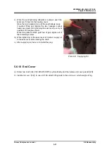
Screw Compressor i-series
7.1 Tightening Angles for Lock Nuts
7-1
Chapter 7 Related Documents
7.1
Tightening Angles for Lock Nuts
On June 14, 2010, the "Lock Nut Tightening Angle Range Control Standard" has been
introduced to our compressor manufacturing division, to control the specified tightening torque
for rotor shaft lock nuts as follows. Accordingly, the tightening angle range is now added to the
rotor shaft lock nut tightening procedure in this manual.
Tightening Angle Range of Lock Nuts for Rotor
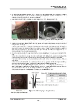
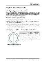
a) After tightening the lock nut by hand, further tighten the lock nut by using a lock nut wrench until the
rotor starts to turn. Take care not to over-tighten.
b) Put a mark on the lock nut at the right side edge of the rotor groove where the stopper tongue of
the lock washer fits in, as shown in Figure 7-1.
c) From this marking position, tighten the lock nut in such a way that rotation can be stopped within
the tightening angle range shown in Table 7-1 (i125/i160: 30°–40°(first time tightening),
20°–30°(second time tightening) for both [39-1] and [39-2]). When measuring the angle, use an
angle gauge which is set to the diameter of rotor shaft.
Table 7-1 Tightening Angles Specified for
Lock Nuts of Rotor
Model
Angle range
First time tightening
i125, i160
30° to 40°
Second time tightening
i125, i160
20° to 30°
* When tightening lock nut, tightening start position differs
between the first time tightening and the tightening for the
second time or after. Therefore, angle ranges are specified
also for the second time tightening.
Figure 7-1
Position where Mark is Put
Marking
Rotor groove (slot)
where stopper tongue
of the lock washer fits


