2200M4JE-HO-iS2-N_2014.04.
Chapter 5 Maintenance
Screw Compressor i-series
5.6 Reassembly
5-21
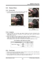
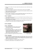
5.6.1 Unloader
a) In the same way as for disassembly, lay main rotor casing
【
1
】
on its side (horizontally).
b) Set unloader cover gasket
【
395
】
, unloader piston
【
391
】
and spring
【
392
】
to unloader cover
【
393
】
.
You can install the unloader piston and spring first.
c) Insert this into the main rotor casing, and tighten
the unloader cover.
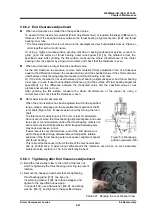
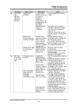
d) Screw an M8 bolt of the maximum allowed length
through the Rc1/4 hole of the unloader cover and
screw it to the unloader piston.
Check that the piston moves properly.
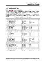
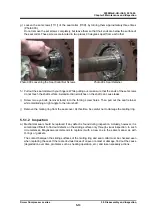
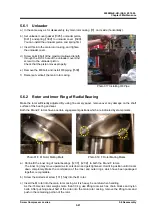
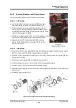
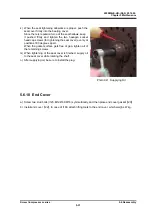
e) Remove the M8 bolt, and install
Φ
8 piping
【
538
】
.
f) Raise (set vertical) the main rotor casing.
Photo 017 Installing
Φ
8 Pipe
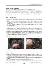
5.6.2 Rotor and Inner Ring of Radial Bearing
Make the rotor sufficiently adjusted. By using fine emery paper, remove over any damage on the shaft
surface of the bearing and seal.
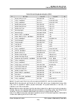
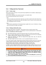
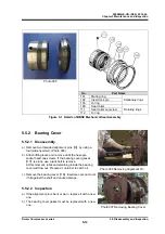
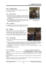
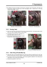
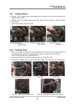
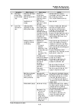
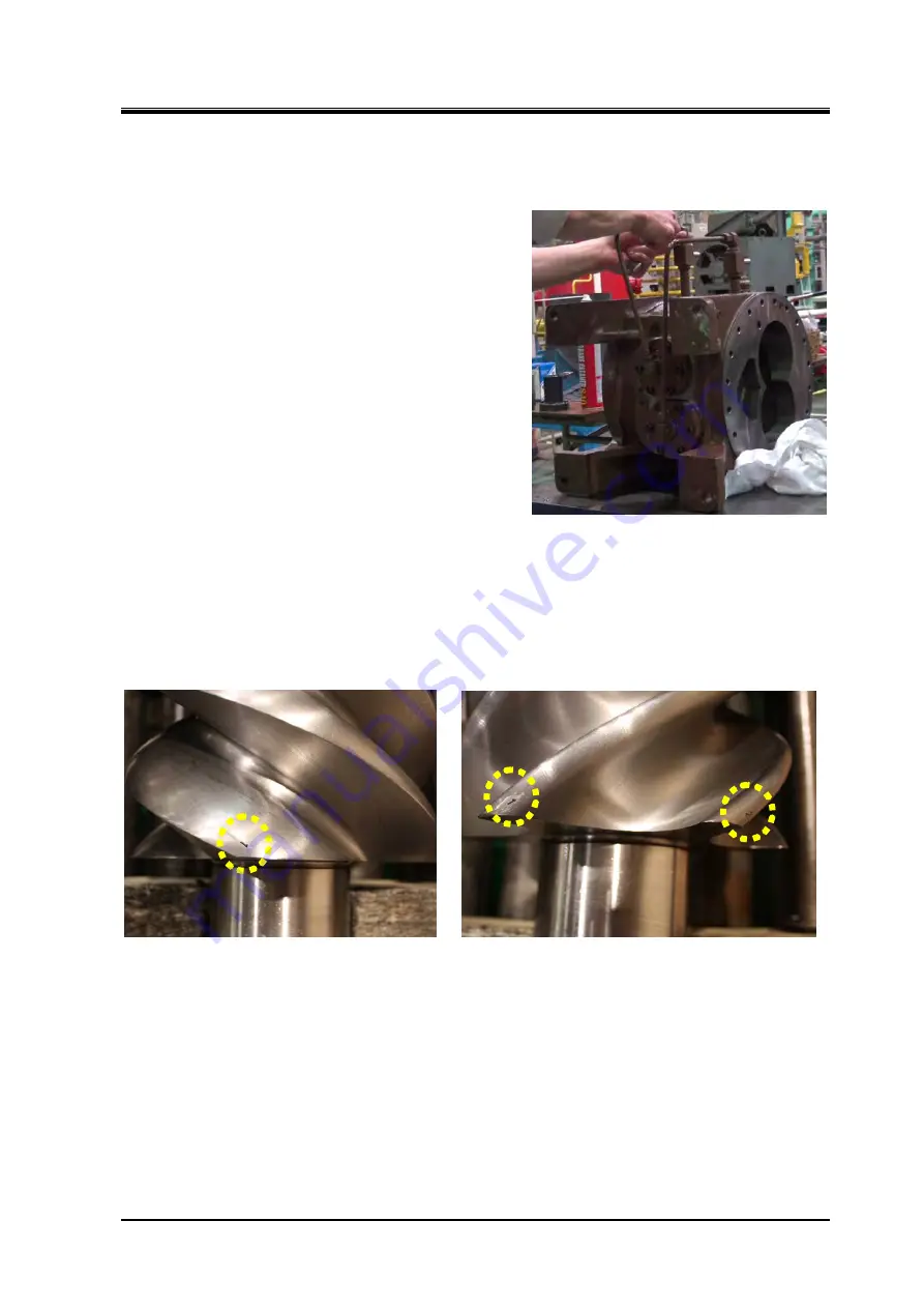
Both the M and F rotors have a certain engagement positions which are indicated by stamp marks.
Photo 018
M Rotor Mating Mark Photo 019
F Rotor Mating Marks
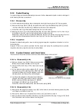
a) Shrink-fit the inner ring of radial bearings
【
27-1
】
【
27-2
】
to both the M and F rotors.
The inner ring may move upward as it cools down and gets tightened. Hold it in position until it cools
down completely. Make the combination of the inner and outer rings, which have been packaged
together, recognizable.
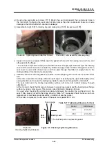
b) Screw the slotted set screw
【
31
】
fully into the M rotor.
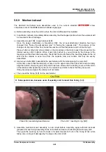
c) Insert the M rotor into the main rotor casing. As it is heavy, be careful when handling.
As the i160-series rotor weighs more than 30 kg, use lifting tools such as chain blocks and nylon
belts. After pushing about half of the rotor into the main rotor casing, remove the lifting tools and
push in the remaining portion of the rotor.


