2200M4JE-HO-iS2-N_2014.04.
Chapter 5 Maintenance and Inspection
Screw Compressor i-series
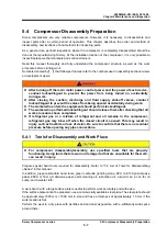
5.5 Disassembly and Inspection
5-16
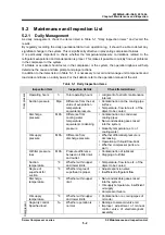
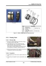
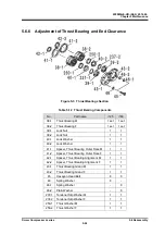
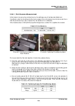
5.5.5 Thrust
Bearings
The thrust bearings
【
38-1
】 【
38-2
】
are face-to-face angular contact ball bearings.
This bearing only receives thrust load and does not receive the radial load perpendicular to the shaft
because there is a gap between the outer ring of the thrust bearing and the bearing head. Apart from
receiving the thrust load, the bearing has the important role of securing the position of the gap between
the rotor and the discharge side of the bearing head. This gap (end clearance) is significantly linked
with performance.
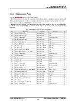
5.5.5.1 Disassembly
Though part sizes differ between the M rotor side and F rotor side, the same work procedure is applied
to both.
a) Remove hexagon head bolts
【
45
】
holding thrust bearing glands
【
43-1
】 【
43-2
】
, and remove the
thrust bearing glands. A spring washer
【
46
】
is attached to the hexagon head bolt. Be careful not to
lose the washer.
As O-rings
【
150-1
】 【
150-2
】
are mounted to the thrust bearing glands used for the i160-series,
they are slightly tight.
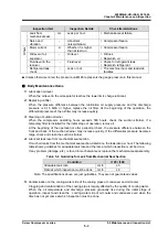
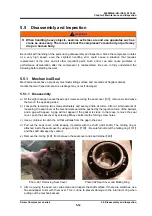
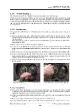
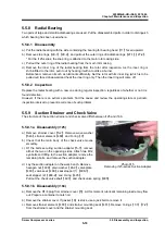
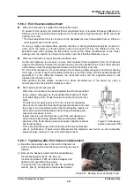
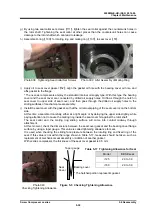
b) Extend the bent claw of lock washers
【
40-1
】 【
40-2
】
.
c) Loosen lock nuts
【
39-1
】 【
39-2
】
by using a dedicated lock nut socket. If, at this moment, the rotor
shaft rotates, attach dedicated rotation stoppers 1 and 2 (refer to sectioon 7.2 in this manual) during
work.
d) Remove lock nuts, torsional slip washers
【
237-1
】 【
237-2
】
and thrust washers
【
250-1
】 【
250-2
】
.
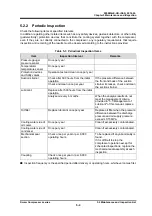
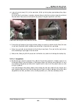
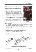
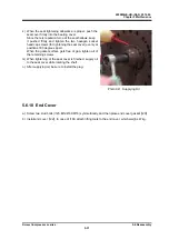
e) Take out thrust bearings
【
38-1
】 【
38-2
】
. Since the inner race of the bearing is slide fit on the rotor
shaft, bend the tip of a wire with diameter of 2 to 3 mm, insert it between the outer ring and the ball
retainer, and hook it onto the thrust bearing to pull it out.
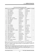
f) Remove thrust bearing outer race spacers
【
41-1
】 【
41-2
】
and thrust bearing alignment spacers
【
42-1
】 【
42-2
】
.
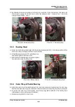
Photo 011 Extending the Claw of Lock Washer Photo 012 Removing the Thrust Bearing
5.5.5.2 Inspection
a) Replace the thrust bearing with a new one during regular inspection, regardless of whether or not it
is defective. If there is an extreme problem, find the cause and review the operating state or periodic
inspection interval to prevent recurrence of such problem.
b) If there is a problem such as extreme deformation in the notch of the lock nut, replace the part with a
new one.
c) Be sure to replace lock washers and torsional slip washers with new ones.
d) O-rings
【
150-1
】 【
150-2
】
attached to the i160-series compressor must be replaced with new ones.


