2200M4-JE-HO-iS2-N_2014.04.
Chapter 2 Compressor Specifications and Configuration
Screw Compressor i-series
2.5
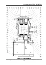
Mechanisms
2-25
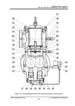
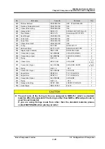
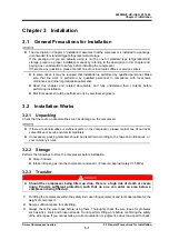
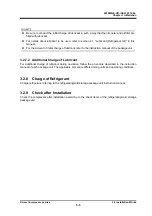
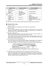
2.5.3 Compression
Process
As the rotors rotate further, the volume between the rotor teeth and grooves decreases while the sealing
line moves toward the discharge side, which compresses the trapped refrigerant gas.
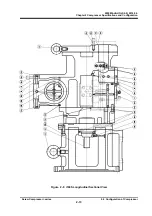
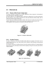
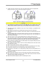
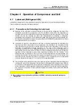
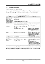
2.5.4 Discharge
Process
The volume between the rotor teeth and grooves decreases to a level predetermined by the discharge
port. With the rotations of the rotors, the compressed refrigerant gas is pushed out to the discharge port.
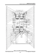
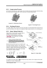
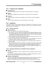
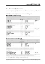
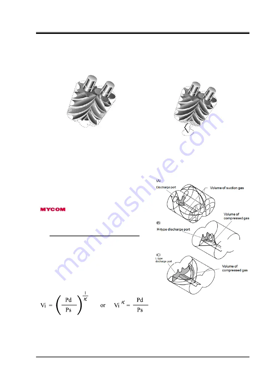
2.5.5 About Volume Ratio (Vi)
Volume ratios (Vi) are indicated in property tables or
catalogs by using port symbols L, M and H.
The volume ratio represented by each symbol
(
screw compressor) is as follows:
L=2.63, M=3.65, H=5.80.
Volume of suctioned refrigerant gas
immediately before the start of compression
Vi =
Volume of refrigerant gas just before pushed
out to discharge port
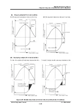
Decide which volume ratio (L, M or H ) should be used
according to operating conditions. If the compressor is
used with a volume ratio that does not match operating
conditions, operation will go inefficiently wasting the power.
The relationship between volume ratios and generally
used compression ratios is as follows:
(Vi)
κ
=
πi
=
Pd/Ps
κ
= Cp/Cv of refrigerant gas
Vi = Design volume ratio πi
= Design compression ratio
Vi is related to the specific heat ratio (
κ
) and therefore its value relative to the compression ratio varies
depending on the type of refrigerant gas.
Figure 2-16
Compression Process
Figure 2-17 Discharge Process
Figure 2-18
Volume Ratio


