background image

Lead

• Adopt suitable measures to avoid the formation of lead dust.
• Switch on extraction system.
• When working with lead or pastes that contain lead, avoid direct contact with the skin. Do not inhale

lead vapors.

• Wash hands after contact with lead or lead-containing substances.

Compressed air

Observe special safety precautions when working with compressed air:
• Unauthorized use of compressed air, e.g. forcing flammable liquids (hazard class AI, AII and B) out of

containers, risks causing an explosion.

• Wear goggles when blowing dirt off workpieces or blowing away swarf.
• Blowing compressed air into thin-walled containers (e.g. containers made of sheet metal, plastic or

glass) for drying purposes or to check for leaks risks bursting them.

• Pay special attention to the pressure in the compressed air system or pressure vessel.
• Assemblies or products to be connected must either be designed for that pressure, or, if the permis-

sible pressure is lower than the system pressure, a pressure reducing valve and safety valve (set to
the permissible pressure) must be connected between the assemblies/products and the system.

• Hose couplings and connections must be securely attached.
• Provide the snout of the air nozzle with a protective disk (e.g. rubber disk).
• First shut off compressed air lines before compressed air device is disconnected from the supply

line, or before device or tool is to be replaced.

• Carry out leak test in accordance with the specifications.

Paints and varnishes

• Observe the relevant safety data sheet for all materials.
• When painting in areas other than spray booths equipped with extractors, ensure good ventilation.

Make sure that neighboring work areas are not adversely affected.

• There must be no naked flames in the vicinity.
• No smoking.
• Observe fire prevention regulations.
• Always wear a mask providing protection against paint and solvent vapors.

Liquid nitrogen

• Observe the relevant safety data sheet for all materials.
• Store liquid nitrogen only in small quantities and always in regulation containers (without gas-tight

caps).

• Avoid body contact (eyes, hands).
• Wear protective clothing, protective gloves, closed shoes and safety goggles.
• Make sure that working area is well ventilated.
• Avoid knocking or jolting the containers, valves and fittings or workpieces in any way.

Acids/alkaline solutions/urea (AdBlue

®

, DEF)

• Observe the relevant safety data sheet for all materials.
• When working with acids and alkaline solutions, wear goggles or face mask, gloves and protective

clothing.

• Do not inhale vapors.
• If urea solution is swallowed, rinse out mouth and drink plenty of water.
• If spilled onto clothing, remove the affected clothing immediately.
• After contact with skin, rinse affected parts of the body with plenty of water.
• Rinse eyes immediately with eyedrops or clean tap water. Seek medical attention as soon as possi-

ble.

MS15018/02E 2013-09

| Safety  | 13

TIM-ID: 0000040536 - 004

Содержание 12 V 2000 G25

Страница 1: ...V 2000 G45 G45 TB 12 V 2000 G65 G65 TB 12 V 2000 G85 G85 TB 16 V 2000 G25 G25 TB 16 V 2000 G45 G45 TB 16 V 2000 G65 G65 TB 16 V 2000 G85 G85 TB 18 V 2000 G25 G25 TB 18 V 2000 G45 G45 TB 18 V 2000 G65...

Страница 2: ...ten permission of MTU Friedrichshafen GmbH This restriction also applies to copyright distribution translation mi crofilming and storage or processing on electronic systems including data bases and on...

Страница 3: ...enset applications 40 6 2 Troubleshooting 64 7 Task Description 7 1 Engine 67 7 1 1 Engine Barring manually 67 7 1 2 Engine Barring with starting system 68 7 1 3 Engine Test run 69 7 2 Cylinder Liner...

Страница 4: ...ge 121 7 16 4 Charge air coolant Level check 122 7 17 Coolant System 123 7 17 1 Cooler Checking cooler elements externally for dirt 123 7 17 2 Cooler Cleaning cooler elements 124 7 18 Battery Charging...

Страница 5: ...ion approved by the manufacturer in writ ing including engine control parameters In compliance with all safety regulations and in adherence with all warning notices in this manual In accordance with t...

Страница 6: ...rk on or around the product This personnel must be instructed repeatedly Personnel requirements All work on the product shall be carried out by trained and qualified personnel only Training at the Tra...

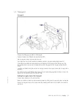
Страница 7: ...for the given weight forklift truck Install the crankshaft locking device and the locking screws for the engine mounts prior to engine trans portation Secure the engine against tilting during transpor...

Страница 8: ...nts and monitoring units must be permanently observed with re gard to present operating status violation of limit values and warning or alarm messages Malfunctions and emergency stop The procedures fo...

Страница 9: ...following applies to starters with copper beryllium alloy pinions Wear breathing protection of filter class P3 during maintenance work Do not blow out the interior of the flywheel housing or the star...

Страница 10: ...erference voltage in the wiring harnesses which could conceivably damage the electrical system Remove parts e g exhaust pipes which are to be welded from the product beforehand Hydraulic installation...

Страница 11: ...on completion of all repair work In partic ular check the function of the engine emergency stop feature Store spare parts properly prior to replacement i e protect them against moisture in particular...

Страница 12: ...product are prohibited by emission regulations Emission control units systems may only be maintained exchanged or repaired if the components used for this purpose are approved by the manu facturer Non...

Страница 13: ...ly line or before device or tool is to be replaced Carry out leak test in accordance with the specifications Paints and varnishes Observe the relevant safety data sheet for all materials When painting...

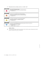
Страница 14: ...event of a situation involving potential danger Consequences Minor or moderate injuries Remedial action NOTICE In the event of a situation involving potentially adverse effects on the product Consequ...

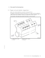
Страница 15: ...ders on the left hand side of the engine and the letter B 3 to refer to the cylinders on the right hand side The cylinders of each bank are numbered consecutively starting with No 1 at the driving end...

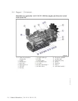
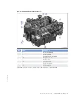
Страница 16: ...rator 3 Intercooler 4 Engine governor 5 Fuel filter 6 Fan drive 7 Oil heat exchanger 8 Oil filter 9 Coolant pump 10 Fuel priming pump 11 Air outlet 12 Exhaust turbocharger 13 Exhaust elbow 14 Charge a...

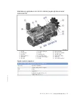
Страница 17: ...ng pump 11 Exhaust turbocharger 12 Oil pan 13 Exhaust elbow 14 Charge air manifold 15 Cylinder head 16 Flywheel housing 17 Mounting 18 Crankcase breather Engine model designation Key to the engine mod...

Страница 18: ...2 B5 Lube oil pressure 3 B9 Charge air coolant temperature 4 B10 Charge air pressure 5 B1 Camshaft speed 6 B13 Crankshaft speed 7 B6 Coolant temperature 8 B33 Fuel temperature The coolant level senso...

Страница 19: ...sure 3 B9 Charge air coolant temperature 4 B10 Charge air pressure 5 B1 Camshaft speed 6 B13 Crankshaft speed 7 B6 Coolant temperature 8 B33 Fuel temperature The coolant level sensor F33 is located in...

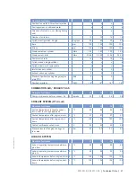
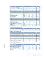
Страница 20: ...100 100 POWER RELATED DATA power ratings are net brake power as per ISO 3046 Number of cylinders 12 12 16 18 Rated engine speed A rpm 1500 1500 1500 1500 Continuous power ISO 3046 10 over load capabil...

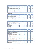
Страница 21: ...8 18 18 18 COMBUSTION AIR EXHAUST GAS Number of cylinders 12 12 16 18 Charge air pressure before cylinder DL R bar abs 2 3 2 5 2 5 2 4 COOLANT SYSTEM HT circuit Number of cylinders 12 12 16 18 Coolant...

Страница 22: ...C 0 0 0 0 Coolant preheating preheating tempera ture min R C 32 32 32 32 Firing speed from R rpm 100 100 100 100 Firing speed to R rpm 120 120 120 120 CAPACITIES Number of cylinders 12 12 16 18 Engine...

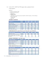
Страница 23: ...ica tion R kg 2490 2490 3100 3500 ACOUSTICS Number of cylinders 12 12 16 18 Exhaust noise unsilenced DL sound power level LW ISO 6798 R dB A 119 119 116 116 Engine surface noise with attenuated in tak...

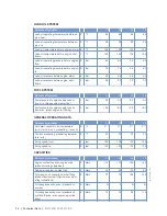
Страница 24: ...l m 100 100 100 100 POWER RELATED DATA power ratings are net brake power as per ISO 3046 Number of cylinders 12 12 16 18 Rated engine speed A rpm 1500 1500 1500 1500 Continuous power ISO 3046 10 over...

Страница 25: ...18 18 COMBUSTION AIR EXHAUST GAS Number of cylinders 12 12 16 18 Charge air pressure before cylinder DL R bar abs 2 3 2 5 2 5 2 4 COOLANT SYSTEM HT circuit Number of cylinders 12 12 16 18 Coolant temp...

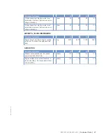
Страница 26: ...Fuel pressure at engine supply connec tion max when engine is starting L bar 0 5 0 5 0 5 0 5 GENERAL OPERATING DATA Number of cylinders 12 12 16 18 Cold start capability Air temperature w o start aid...

Страница 27: ...WEIGHTS MAIN DIMENSIONS Number of cylinders 12 12 16 18 Engine weight dry basic engine configu ration acc to scope of supply specifica tion R kg 2570 2570 3180 3580 ACOUSTICS Number of cylinders 12 12...

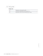
Страница 28: ...ng order 12 V A1 B2 A5 B4 A3 B1 A6 B5 A2 B3 A4 B6 16 V A1 B5 A3 A5 B2 B8 A2 A8 B3 A7 B4 B6 A4 A6 B1 B7 18 V A1 B6 A3 B4 A5 B2 A7 B1 A9 B3 A8 B5 A6 B7 A4 B9 A2 B8 28 Technical Data MS15018 02E 2013 09...

Страница 29: ...dth B Height C 12 V 2000 Gxy approx 1885 mm approx 1580 mm approx 1585 mm 16 V 2000 Gxy approx 2230 mm approx 1580 mm approx 1585 mm 18 V 2000 Gxy approx 2400 mm approx 1580 mm approx 1620 mm MS15018...

Страница 30: ...uel prefilter pressure gauge Align adjustable pointer with position of pressure indicator Page 97 Fuel system Vent Page 94 Coolant circuit If engine is out of service for more than one year change eng...

Страница 31: ...109 Cooling system Check engine coolant level Page 112 Check charge air coolant level Page 122 Cooling system Preheat coolant with preheating unit Fuel prefilter Drain Page 98 Monitoring equipment Ca...

Страница 32: ...if fitted Switch on Starting the engine Item Action Switchgear cabinet control panel etc depending on manufacturer If coolant temperature is 40 C with preheating system or 5 C without preheating syste...

Страница 33: ...when a pushbutton is provided Safety system Override Item Action Switchgear cabinet control panel etc depending on manufacturer Activate pushbutton for Override input of the ECU Certain shutdown crit...

Страница 34: ...noises and vibration Fuel prefilter Check whether indicated differential pressure is within the limit Page 97 Exhaust system Check exhaust color Page 64 Intercooler Check condensate drain s for water...

Страница 35: ...fter the generator breaker if provided has been opened allow the engine to cool down by running it idle for approx 5 minutes Preparing a pump drive diesel mechanical diesel electric Item Action Engine...

Страница 36: ...tem Action Emergency stop pushbutton Press pushbutton Engine is stopped by disconnecting the power supply to the ECU signalization e g by horn flashing lamp is released After emergency stop from LOP I...

Страница 37: ...he engine Engine remains ready for operation After stopping the engine Item Action Engine generator pump control Select operating mode e g MANUAL AUTOMATIC OPERATION MS15018 02E 2013 09 Operation 37 T...

Страница 38: ...o the coolant the engine room is not heated the coolant is not kept at a suitable temperature the antifreeze concentration is insufficient for the engine room tem perature antifreeze concentration is...

Страница 39: ...minants from fuel prefilter Page 34 W0508 Check reading on differential pressure gage of fuel prefilter Page 34 W0534 Carry out test run minimum duration until steady state tem perature is reached no...

Страница 40: ...rred e g nd11 Second line option Running text providing more information about the fault currently displayed Time indicator for alarms Meaning Alarm is no longer active does not appear on next power u...

Страница 41: ...Module Slot5 Defect 24 I O Module Slot6 Defect 25 I O Module Slot7 Defect 26 I O Module Slot8 Defect 27 Download Server Collision 28 not projected node Engine governor messages Recommended action in c...

Страница 42: ...e below lists possible fault codes Fault code no Full designation Meaning Action Setting parame ter no 003 HI T Fuel Prewarning Fuel tempera ture too high limit value 1 alarm configuration parame ter...

Страница 43: ...8008 100 for explanation Automatic en gine shutdown Check oil level con tact Service 2 0100 922 024 SS Coolant Level Coolant level too low limit value 2 alarm configuration parameter see PR 2 8008 100...

Страница 44: ...leaking alarm configuration parame ter see PR 2 8008 100 for explanation On stopping Seal off system contact Service On starting Check engine for leakage if none found attempt re starting as per oper...

Страница 45: ...arameter see PR 2 8008 100 for explanation Engine start inter lock is active as coolant temperature is too low for engine start preheating necessary 2 1090 921 095 AL Prelubrication Fault Oil priming...

Страница 46: ...or CAN bus to backup system is dis rupted alarm configuration parameter see PR 2 8008 100 for explanation Contact Service 2 4000 004 177 AL LifeData restore in complete This fault message is gener ate...

Страница 47: ...warning Causes are e g missing associate nodes mi nor disruptions and tempora ry bus overload alarm con figuration parameter see PR 2 8008 100 for explanation Contact Service 2 0500 687 188 AL CAN2 B...

Страница 48: ...pressure sensor faulty HP controller in emergency mode short circuit or wire break Check sensor and wiring B48 replace as necessary 1 8004 567 216 SD T Lube Oil SD alarm configuration lube oil temper...

Страница 49: ...ration cam shaft sensor faulty short cir cuit or wiring damage engine remains operational Check sensor and wiring B1 attempt restart fault may be rectified when en gine is restarted Contact Service if...

Страница 50: ...mp if this occurs frequently 1 8004 502 304 AL Timing Cylinder A4 Time of flight measuring fault injector cylinder A4 Time of flight value measured ex tremely small or large alarm configuration parame...

Страница 51: ...B1 Time of flight measuring fault injector cylinder B1 Time of flight value measured ex tremely small or large alarm configuration parameter see PR 2 8008 100 for explana tion Replace plug in pump if...

Страница 52: ...ctor cylinder B8 Time of flight value measured ex tremely small or large alarm configuration parameter see PR 2 8008 100 for explana tion Replace plug in pump if this occurs frequently 1 8004 517 319...

Страница 53: ...itive to negative e g by exchanging injec tors Fault rectifica tion When engine is restarted 1 8004 523 325 AL Wiring Cylinder A5 Wiring fault in injector wiring cylinder A5 Result Misfiring alarm con...

Страница 54: ...sitive to negative e g by exchanging injec tors Fault rectifica tion When engine is restarted 1 8004 529 331 AL Wiring Cylinder B1 Wiring fault in injector wiring cylinder B1 Result Misfiring alarm co...

Страница 55: ...itive to negative e g by exchanging injec tors Fault rectifica tion When engine is restarted 1 8004535 337 AL Wiring Cylinder B7 Wiring fault in injector wiring cylinder B7 Result Misfiring alarm conf...

Страница 56: ...de disrup tion in solenoid valve e g by injec tor replacement Fault rectification After each working cycle 1 8004 541 343 AL Open Load Cylinder A3 Disruption fault in injector wiring cylinder A3 Resul...

Страница 57: ...in solenoid valve e g by injec tor replacement Fault rectification After each working cycle 1 8004 547 349 AL Open Load Cylinder A9 Disruption fault in injector wiring cylinder A9 Result Misfiring ala...

Страница 58: ...in solenoid valve e g by injec tor replacement Fault rectification After each working cycle 1 8004 553 355 AL Open Load Cylinder B5 Disruption fault in injector wiring cylinder B5 Result Misfiring al...

Страница 59: ...ve If parameter 1 1020 021 Pow er Stage Failure Stop En gine is set engine is stop ped here additionally alarm configuration parameter see PR 2 8008 100 for explana tion Start engine gover nor self te...

Страница 60: ...ring TOP 3 Short circuit or wire break at transistor output 3 plant side TOP 3 alarm configuration parameter see PR 2 8008 100 for explanation Check wiring 2 8006 640 384 AL Wiring TOP 4 Short circuit...

Страница 61: ...ty or no re sistance via switch alarm configuration parameter see PR 2 8008 100 for explana tion Check wiring 2 8006 631 407 AL Open Load Digital Input 8 Line disruption at digital in put 8 wiring fau...

Страница 62: ...ure Alarm con figuration parameter see PR 2 8008 100 for explanation None 2 7000 011 463 SD AUX 2 SD alarm configuration ana log input signal for Aux 2 faulty short circuit or wiring damage Check sign...

Страница 63: ...rror of crash re corder Contact Service 1 8010 007 478 AL Comb Alarm Yel Plant YELLOW combined alarm from plant alarm configura tion parameter see PR 2 8008 100 for explanation Contact Service 2 8006...

Страница 64: ...rotation by starter Battery low or defective Charge or replace battery see manufac turer s documentation Engine wiring Defective Check Page 133 Fuel system Not vented Vent fuel system Page 94 Engine...

Страница 65: ...position of service in dicator Page 107 Intercooler Contaminated Contact Service Exhaust turbocharger Defective Contact Service Coolant leaks on intercooler Component Probable Cause Task Intercooler L...

Страница 66: ...t at operating temperature Run engine to reach operating tempera ture Fuel system Water in fuel Check fuel system on fuel prefilter Drain fuel prefilter Page 98 Intercooler Leaking Contact Service 66...

Страница 67: ...persons in the engine s danger zone After finishing work on the engine make sure that all safety devices are put back in place and all tools removed from the engine Engine Barring manually 1 Remove a...

Страница 68: ...Before cranking the engine with starter system make sure that there are no persons in the en gine s danger zone Engine Barring with starting system 1 Press pushbutton Bar engine without starting and k...

Страница 69: ...no persons in the en gine s danger zone WARNING High level of engine noise when the engine is running Risk of damage to hearing Wear ear protectors Engine Test run 1 Start engine Page 32 2 Perform te...

Страница 70: ...s First signs of marks left by lower cooling bores Running pattern seems darker No action required Dark areas with even or varying degrees of discoloration Beginning and end of the discoloration are n...

Страница 71: ...Final steps 1 Install injector Page 86 2 Install cylinder head cover Page 80 MS15018 02E 2013 09 Task Description 71 TIM ID 0000000015 014...

Страница 72: ...und the liner It appears rather darker within the honed struc ture in contrast to the bright metallic running surface The honing pattern is undis turbed Discolorations extend in stroke direction and m...

Страница 73: ...ation are similar A thorough investigation and compliance with the above evaluation criteria allow an unambiguous evaluation To avoid unnecessary disassembly work it is recommended that another inspec...

Страница 74: ...residues which are harmful to health Risk of injury and poisoning Wear protective clothing gloves and goggles safety mask Avoid contact with skin Do not inhale oil vapor Replacing oil separator elemen...

Страница 75: ...aphragm 3 on housing 1 5 Install new seal 2 and spring 5 together with cover 4 6 Use torque wrench to tighten the screws of cover 4 to the specified torque Name Size Type Lubricant Value Standard Scre...

Страница 76: ...components is possible Observe manufacturer s instructions Crankcase breather Wire mesh cleaning 1 Remove hose 2 Loosen clamp 5 3 Remove oil separator cover 7 4 Remove individual parts from oil separ...

Страница 77: ...t No Qty Feeler gauge Y4342013 1 Torque wrench 20 100 Nm F30026582 1 Ratchet F30027340 1 Engine oil Preparatory steps 1 Remove cylinder head cover Page 80 2 Install barring device Page 67 3 Bar engine...

Страница 78: ...piston is in overlap TDC 2 Check valve clearance with cold engine Inlet 0 4 mm Exhaust 0 6 mm 3 Check all valve clearances in two crankshaft positions firing TDC and overlap TDC of cylinder A1 as per...

Страница 79: ...ied tightening torque while holding adjusting screw 2 firmly with screw driver Name Size Type Lubricant Value Standard Locknut M12 x 1 Tightening torque Engine oil 50 Nm 5 Insert feeler gauge between...

Страница 80: ...nkcase breather Loosen clamps 2 Slide rubber sleeves onto the pipe Cylinder head cover Removal and installation 1 Remove cylinder head cover 2 with gas ket 1 from cylinder head 2 Clean installation su...

Страница 81: ...eplacement Special tools Material Spare parts Designation Use Part No Qty Injection pump Spare Parts Catalog Injection pump Replacement u Remove injection pump and install new one Page 82 MS15018 02E...

Страница 82: ...Gasket Spare Parts Catalog DANGER Rotating and moving engine parts Risk of crushing danger of parts of the body being caught or pulled in Before cranking the engine with starter system make sure that...

Страница 83: ...p head 5 Remove injection pump securing screws 6 Remove injection pump 7 Remove sealing rings from injection pump 8 After removal seal all openings with suita ble covers Injection pump Installation 1...

Страница 84: ...g torque Engine oil 35 Nm 3 Nm 13 Tighten union nuts 2 4 marked with 30 3 Nm see arrow with torque wrench to the specified tight ening torque Name Size Type Lubricant Value Standard Union nut M14 Tigh...

Страница 85: ...tor Replacement Special tools Material Spare parts Designation Use Part No Qty Injector Spare Parts Catalog Replacing injector u Remove injector and install new injector Page 86 MS15018 02E 2013 09 Ta...

Страница 86: ...ling ring Spare Parts Catalog Gasket Spare Parts Catalog WARNING Fuels are combustible Risk of fire and explosion Avoid open flames electrical sparks and ignition sources Do not smoke WARNING Compress...

Страница 87: ...on 1 Remove all covers before installation 2 Clean sealing surface on cylinder head and protective sleeve 3 Coat sealing ring 1 with grease and fit on to injector 4 Coat sealing ring 2 with grease and...

Страница 88: ...read on both ends of the fuel line 2 with engine oil 16 Install fuel line 2 Note Observe the inscription on the union nuts 1 3 17 Tighten union nuts 1 3 marked with 35 3 Nm see arrows with torque wren...

Страница 89: ...Spare Parts Catalog Gasket Spare Parts Catalog WARNING Fuels are combustible Risk of fire and explosion Avoid open flames electrical sparks and ignition sources Do not smoke WARNING Compressed air gu...

Страница 90: ...line 2 Note Observe the inscription on the union nuts 1 3 11 Tighten union nuts 1 3 marked with 35 3 Nm see arrows with torque wrench to the specified tightening torque Name Size Type Lubricant Value...

Страница 91: ...m F30028341 1 Engine oil WARNING Fuels are combustible Risk of fire and explosion Avoid open flames electrical sparks and ignition sources Do not smoke Fuel Draining 1 Loosen nut arrow on banjo union...

Страница 92: ...with torque wrench to the specified tight ening torque Name Size Type Lubricant Value Standard Non return valve Tightening torque Engine oil 10 Nm 1 Nm 5 Connect fuel line 6 Tighten nut on banjo unio...

Страница 93: ...of fire and explosion Avoid open flames electrical sparks and ignition sources Do not smoke Fuel pressure maintaining valve Removal and installation 1 Shut off fuel supply 2 Remove fuel line 6 3 Remo...

Страница 94: ...are combustible Risk of fire and explosion Avoid open flames electrical sparks and ignition sources Do not smoke Fuel system Venting 1 Unlock fuel priming pump unscrew handle 2 Loosen nut arrow on ba...

Страница 95: ...10 Operate the pump with the handle until bubble free fuel emerges 11 Use torque wrench to non return valve to the specified tightening torque Name Size Type Lubricant Value Standard Non return valve...

Страница 96: ...og WARNING Fuels are combustible Risk of fire and explosion Avoid open flames electrical sparks and ignition sources Do not smoke Fuel filter Replacement 1 Remove easy change filter using the filter w...

Страница 97: ...if ferential pressure gauge 1 After installation of a new filter element align adjustable pointer 2 with pressure indicating pointer 3 of pressure gauge 1 2 Verify that differential pressure is within...

Страница 98: ...e drained 1 Left filter cut in 2 Right filter cut in 2 Open threaded vent plug 5 of filter to be drained 3 Unlock drain valve 6 by pressing toggle and open it 4 Drain water and contaminants from filte...

Страница 99: ...e at low power Keep away from the engine s danger zone WARNING Fuels are combustible Risk of fire and explosion Avoid open flames electrical sparks and ignition sources Do not smoke WARNING High level...

Страница 100: ...refilter Filling with fuel 1 Stop engine Page 35 and disable engine start 2 Remove screws securing the cover and take off cover 2 3 Fill filter housing with clean fuel 4 Place new gasket in cover 2 5...

Страница 101: ...Cleaning 1 Close fuel supply 2 Remove nuts from filter head 3 Unscrew filter bowl and drain fuel into a suitable container 4 Remove securing nut for filter element and pull off filter element downwar...

Страница 102: ...Diesel fuel Filter element Spare Parts Catalog Gasket Spare Parts Catalog WARNING Fuels are combustible Risk of fire and explosion Avoid open flames electrical sparks and ignition sources Do not smok...

Страница 103: ...2 7 Remove spring housing 4 and filter ele ment 3 8 Insert new filter element 3 and spring housing 4 9 Fill filter housing with clean fuel 10 Place new gasket in cover 2 11 Fit cover with gasket and s...

Страница 104: ...ear defenders Checking intercooler condensate drain for coolant discharge and obstructions 1 Remove plug screw s from charge air manifold 2 Check drain bore s for air discharge If no air escapes 3 Cl...

Страница 105: ...rt No Qty Air filter Spare Parts Catalog Filter insert Spare Parts Catalog Filter element Spare Parts Catalog Air filter Replacement 1 Remove air filter s and install new one s Page 106 2 Reset signal...

Страница 106: ...the intake housing 3 and clean it 4 Fit air filter 1 and clamp 2 on connecting flange of intake housing 3 5 Tighten clamp 2 Variant B 1 Release latches 1 2 Take off cover 2 3 Remove filter insert 3 a...

Страница 107: ...ecking signal ring position 1 Replace air filter if the signal ring 2 is completely visible in the red area of the service indicator control window 3 Page 105 2 After installation of new filter press...

Страница 108: ...stem make sure that there are no persons in the en gine s danger zone WARNING High level of engine noise when the engine is running Risk of damage to hearing Wear ear protectors Air starter Manual ope...

Страница 109: ...1 marks 4 Top up with oil up to the max 1 mark Page 110 if required 5 Insert oil dipstick into guide tube up to the stop Oil level check after the engine is stopped 1 5 minutes after stopping the engi...

Страница 110: ...and pump Draining oil at drain plug on oil pan 1 Provide a suitable container to collect the oil 2 Remove drain plug and drain oil 3 Install drain plug with new sealing ring 4 Replace engine oil filte...

Страница 111: ...Wear protective clothing gloves and goggles safety mask Avoid contact with skin Do not inhale oil vapor Engine oil filter Replacement 1 Remove oil filter with filter wrench 2 Clean the sealing face o...

Страница 112: ...coolant expansion tank counterclockwise to the first stop and allow pressure to escape 2 Continue to turn breather valve counter clockwise and remove 3 Check coolant level coolant must be visi ble at...

Страница 113: ...pecial tools Material Spare parts Designation Use Part No Qty Engine coolant Engine coolant Change 1 Drain engine coolant Page 114 2 Fill with engine coolant Page 115 MS15018 02E 2013 09 Task Descript...

Страница 114: ...itch off preheating unit Engine coolant Draining 1 Turn breather valve on coolant expansion tank counterclockwise to the first stop and allow pressure to escape 2 Continue to turn breather valve count...

Страница 115: ...OTICE Cold coolant in hot engine can cause thermal stress Possible formation of cracks in the engine Fill top up coolant only into cold engine Preparatory steps 1 Turn breather valve on coolant expans...

Страница 116: ...inal steps 1 Start the engine and operate it at idle speed for some minutes 2 Check coolant level Page 112 top up with coolant if required 116 Task Description MS15018 02E 2013 09 TIM ID 0000000034 00...

Страница 117: ...rs Coolant pump Relief bore check 1 Check relief bore for oil and coolant dis charge 2 Permissible discharge Up to 10 drops of coolant per hour Up to 5 drops of oil per hour 3 If discharge exceeds the...

Страница 118: ...oves and goggles safety mask WARNING High level of engine noise when the engine is running Risk of damage to hearing Wear ear protectors NOTICE Cold coolant in hot engine can cause thermal stress Poss...

Страница 119: ...ing plate 2 Install plug screws of filling points with new sealing rings 3 Check proper condition of breather valve clean sealing faces if required 4 Fit breather valve and close it Final steps 1 Star...

Страница 120: ...priate container to drain the coolant into 2 Turn breather valve on coolant expansion tank counterclockwise to the first stop and allow pressure to escape 3 Continue to turn breather valve counter clo...

Страница 121: ...pecial tools Material Spare parts Designation Use Part No Qty Coolant Charge air coolant Change 1 Drain charge air coolant Page 120 2 Fill with charge air coolant Page 118 MS15018 02E 2013 09 Task Des...

Страница 122: ...clockwise to the first stop and allow pressure to escape 2 Continue to turn breather valve counter clockwise and remove 3 Check coolant level coolant must be visi ble at marking plate 4 Top up coolant...

Страница 123: ...nally for dirt Preconditions Engine is stopped and starting disabled Check cooler elements externally for dirt 1 Inspect cooler elements visually for dirt 2 Clean badly soiled cooler elements Page 124...

Страница 124: ...agents on components Damage to component Observe manufacturer s instructions Wear protective clothing gloves and goggles safety mask CAUTION Unsuitable cleaning tool Damage to component Observe manufa...

Страница 125: ...en around the entire cir cumference A If rib material is broken off in some pla ces B 4 Install protective cover Drive belt Tension check 1 Remove protective cover 2 Position pretension gauge on drive...

Страница 126: ...Tension drive belt with tensioning nut 1 and check belt tension 3 Tighten screw 2 to specified torque using a torque wrench Name Size Type Lubricant Value Standard Screw M18 Tightening torque Engine o...

Страница 127: ...e Page 131 3 Release securing screws 2 3 4 Release tensioning screw 1 until the drive belt can be removed 5 Check belt pulleys for cleanliness remove dirt if any 6 Fit new drive belt 7 Tension drive b...

Страница 128: ...ng If belt is cracked If belt is worn If cracks are found Drive belt Tension check var iant A 1 Place belt tension tester onto drive midway between the belt pulleys arrow 2 Press button uniformly agai...

Страница 129: ...lue at the intersec tion of indication arm and KG scale 6 If the measured value deviates from the specified setting readjust belt tension Setting new drive belt 670 N 50 N Setting used drive belt 570...

Страница 130: ...to tension drive belt 3 Check drive belt tension 4 Tighten screws 1 4 with torque wrench to the specified tightening torque Name Size Type Lubricant Value Standard Screw M18 Tightening torque Engine o...

Страница 131: ...grooves as a set and without applying any force 5 Fit new set of drive belts 6 To check drive tension the fan bearing pedestal must rest against the gearcase 7 Adjust and check drive belt tension Page...

Страница 132: ...Final steps 1 Install fan 2 Install protective cover 132 Task Description MS15018 02E 2013 09 TIM ID 0000000046 003...

Страница 133: ...swing freely 3 Check that cable clamps are firm tighten loose cable clamps 4 Replace faulty cable clamps 5 Visually inspect the following electrical line components for damage Connector housing Conta...

Страница 134: ...ove coarse dirt from housing surface using a cloth moistened with isopropyl alcohol 2 Remove dirt from the connector and cable surfaces with isopropyl alcohol 3 Check legibility of cable labels Clean...

Страница 135: ...itable test probe e g test prod The contacts in the plug connection can be bent Carry out check of plug connection only with test connectors Checking plug connections at engine governor 1 Check all pl...

Страница 136: ...governor from engine 1 Note or mark assignment of cables and connectors 2 Remove all screws 2 3 Undo latches 3 of the connectors 4 Disconnect all connectors 5 Remove screws 1 6 Take off engine governo...

Страница 137: ...p rectify fault as soon as possible 2nd function Read out fault codes CKT Circuit CLS Coolant Level Sensor Monitors coolant level CM Current Measurement Current measured value CPS Coolant Pressure Sen...

Страница 138: ...Alarm Measured value exceeds 1st maximum limit value HIHI High High Alarm Measured value exceeds 2nd maximum limit value HT High Temperature High temperature IDM Interface Data Module Memory module fo...

Страница 139: ...ng lamp stop engine and rectify fault 2nd function Read out fault codes SID System Identification SRS Synchronous Reference Sensor OT cylinder 1 SS Safety System Security Shutdown Safety system alarm...

Страница 140: ...e work in case of malfunction or changed operating conditions or for spare parts supply Your contact person in our Customer Assistance Center E mail info mtu online com Tel 49 7541 9077777 Fax 49 7541...

Страница 141: ...d installation Page 86 Qty Used in 1 7 7 1 Fuel injection line Pressure pipe neck replace ment Page 89 Barring device for 12V engines Part No F6558556 Qty Used in 1 7 1 1 Engine Barring manually Page...

Страница 142: ...l and installation Page 82 Qty Used in 1 7 6 2 Injector Removal and installation Page 86 Qty Used in 1 7 7 1 Fuel injection line Pressure pipe neck replace ment Page 89 Crowfoot wrench 19 mm Part No F...

Страница 143: ...gauge Part No Y4342013 Qty Used in 1 7 4 1 Valve clearance Check and adjustment Page 77 Filter wrench Part No F30379104 Qty Used in 1 7 8 1 Fuel filter Replacement Page 96 Qty Used in 1 7 14 1 Engine...

Страница 144: ...0025897 Qty Used in 1 7 6 2 Injector Removal and installation Page 86 Qty Used in 1 7 7 1 Fuel injection line Pressure pipe neck replace ment Page 89 Pre tension gauge Part No Y20097429 Qty Used in 1...

Страница 145: ...Used in 1 7 6 2 Injector Removal and installation Page 86 Qty Used in 1 7 7 1 Fuel injection line Pressure pipe neck replace ment Page 89 Qty Used in 1 7 18 1 Battery charging generator drive Drive b...

Страница 146: ...Qty Used in 1 7 7 1 Fuel injection line Pressure pipe neck replace ment Page 89 Qty Used in 1 7 18 1 Battery charging generator drive Drive belt check and adjustment Page 125 Qty Used in 1 7 18 2 Bat...

Страница 147: ...wrench 8 40 Nm Part No F30043446 Qty Used in 1 7 4 2 Cylinder head cover Removal and installation Page 80 Qty Used in 1 7 7 2 Fuel Draining Page 91 MS15018 02E 2013 09 Appendix B 147 DCL ID 000001946...

Страница 148: ...nt Change Page 121 Diesel fuel Part No Qty Used in 7 3 2 Crankcase breather Wire mesh cleaning Page 76 Qty Used in 7 8 1 Fuel filter Replacement Page 96 Qty Used in 7 8 3 Fuel prefilter Draining Page...

Страница 149: ...ty Used in 7 18 1 Battery charging generator drive Drive belt check and adjustment Page 125 Qty Used in 7 18 2 Battery charging generator drive Drive belt replacement Page 127 Qty Used in 7 19 1 Fan d...

Страница 150: ...Petroleum jelly Part No Qty Used in 7 3 2 Crankcase breather Wire mesh cleaning Page 76 150 Appendix B MS15018 02E 2013 09 DCL ID 0000019467 004...

Страница 151: ...Qty Used in 7 19 2 Fan drive Belt replacement Page 131 Easy change filter Part No Qty Used in 7 8 1 Fuel filter Replacement Page 96 Filter element Part No Qty Used in 7 3 1 Crankcase breather Oil sep...

Страница 152: ...ining Page 98 Qty Used in 7 8 6 Fuel prefilter Filter element replacement Page 102 Injection pump Part No Qty Used in 7 5 1 Injection pump Replacement Page 81 Injector Part No Qty Used in 7 6 1 Inject...

Страница 153: ...93 Qty Used in 7 7 3 Fuel pressure maintaining valve Removal and installation Page 93 Qty Used in 7 8 5 Fuel prefilter Cleaning Page 101 Qty Used in 7 9 1 Intercooler Checking condensate drain for co...

Страница 154: ...76 Cylinder Designation 15 Cylinder head cover Removal and installation 80 Cylinder liner Endoscopic examination 70 Instructions and comments on endoscopic and visual examination 72 D Designations Eng...

Страница 155: ...persons 140 O Operational checks 34 P Putting the engine into operation after extended out of service periods 3 months 30 Putting the engine into operation after scheduled out of service period 31 S...

Отзывы: