

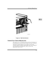


3 1/2- or 5 1/4-Inch Drive Modules
4-9
4
3
1
/
2
-
or 5
1
/
4
-Inch Drive Modules
The SCSI peripheral expansion enclosure contains up to four half-
height storage devices. Two bays accommodate 3
1
/
2
-inch devices
only. The other two bays accommodate either 3
1
/
2
-inch or 5
1
/
4
-inch
devices.
The suggested procedure for removal and replacement of 3
1
/
2
- or
5
1
/
4
-inch drive modules is as follows:
Removal
1. Switch the power supply of the host system to
STANDBY
.
2. Disconnect the input power source from the XR900 chassis:
– If the power supply is an AC unit, unplug the power cord
from the AC outlet.
– If the power supply is a DC unit, turn off the –48Vdc
power source and unplug the DC connector from the
power supply input.
3. Remove the XR900 bezel, if installed.
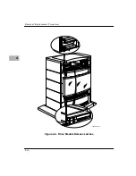
4. While pressing the latch at the side of the drive carrier (Figure
5-4), move the module back and forth slightly to loosen the
backplane connection. Then carefully remove the module
from the chassis by pulling straight out.
Содержание XR900 Series
Страница 1: ...XR900 Series Mass Storage Subsystem User s Manual MCPIOSA UM2 ...
Страница 9: ...x ...
Страница 11: ...xii ...
Страница 43: ...Operating Instructions 3 10 3 ...
Страница 46: ...Front Bezel 4 3 4 Figure 4 1 Bezel Removal 11051 00 9408 BEZEL LOCKS 1 EACH SIDE LATCH BUTTONS 1 EACH SIDE ...
Страница 53: ...Removal Replacement Procedures 4 10 4 Figure 4 4 Drive Module Release Latches 11060 00 9409 ...
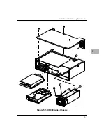
Страница 57: ...Parts List and Ordering Information 5 3 5 Figure 5 1 XR900 Series Chassis 11271 00 9503 1 3 2 4 ...
Страница 58: ...Support Information 5 4 5 ...