


Hardware Preparation and Installation
2-8
2
Cabling
After you have completed the rack or pedestal installation of the
XR900 chassis and associated equipment, proceed as follows to
cable the hardware together.
Note
All rack cabling should be contained within the rack
bay. Cabling to external peripheral equipment should
be routed through the rear panel of the rack.
Data/Control Cables
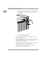
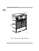
1. Attach one end of an SCSI cable to the lower of the two 68-pin
connectors labeled
SCSI
on the back of the XR900 chassis
(Figure 2-5).
Note
For the differential enclosure, make sure the cabling is
connected to a differential controller.
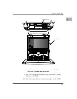
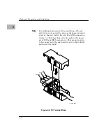
2. Locate the upper SCSI connector on the back of the existing
integral SCSI peripheral expansion chassis (if one is present)
or the appropriate SCSI connector on the back of the Modular
Chassis. Remove the terminator block and plug the other end
of the SCSI cable into that connector.
3. Move the terminator block to the unused upper SCSI
connector on the XR900 chassis.
Note
On the differential enclosure, you must use a
differential terminator.
4. To connect the environmental monitor circuitry, attach an
RJ45 cable to the lower of the two RJ45 connectors (identified
Содержание XR900 Series
Страница 1: ...XR900 Series Mass Storage Subsystem User s Manual MCPIOSA UM2 ...
Страница 9: ...x ...
Страница 11: ...xii ...
Страница 43: ...Operating Instructions 3 10 3 ...
Страница 46: ...Front Bezel 4 3 4 Figure 4 1 Bezel Removal 11051 00 9408 BEZEL LOCKS 1 EACH SIDE LATCH BUTTONS 1 EACH SIDE ...
Страница 53: ...Removal Replacement Procedures 4 10 4 Figure 4 4 Drive Module Release Latches 11060 00 9409 ...
Страница 57: ...Parts List and Ordering Information 5 3 5 Figure 5 1 XR900 Series Chassis 11271 00 9503 1 3 2 4 ...
Страница 58: ...Support Information 5 4 5 ...


