


Hardware Preparation and Installation
2-14
2
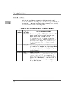
Chassis Cooling Considerations
It is essential that all modules used in the system be properly
cooled. The following information is supplied to help determine
whether the cooling is adequate.
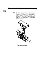
Modular Chassis equipment, including the XR900 chassis, is
designed for an input air temperature below 50
°
C (122
°
F). The
XR900’s DC-powered fan provides forced-air cooling for the power
supply module and mass storage drives. Cooling air is drawn in the
front of the module and vented out through the lower back panel of
the chassis.
Note that for tape storage media, a maximum safe temperature of
50
°
C (122
°
F) is specified. Since the operating temperatures within
the chassis will always be greater than the air inlet temperature,
avoid using tapes if the inlet temperature exceeds 40
°
C (104
°
F).
To provide adequate cooling:
❏
The air space behind the chassis must not be blocked, and the
fan inlet screen must be clean.
❏
The air inlet temperature must not exceed 50
°
C/122
°
F (or
40
°
C/104
°
F if storage tapes are used). When the XR900 is
installed in a rack with other chassis, be sure that each chassis
in the rack is provided with its own supply of cooling air. Do
not use air heated by one chassis to “cool” another chassis.
❏
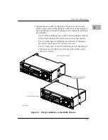
In rack installations, the side and back panels of the rack must
be in place. All unoccupied rack mount locations must be
covered with blank bezels.
The system is designed for use in a relatively clean (office or lab)
environment. To assure reliable operation in an industrial
environment, you may need to provide protection against airborne
particles and other contaminants, especially for the disk or tape
drives and their associated media.
Содержание XR900 Series
Страница 1: ...XR900 Series Mass Storage Subsystem User s Manual MCPIOSA UM2 ...
Страница 9: ...x ...
Страница 11: ...xii ...
Страница 43: ...Operating Instructions 3 10 3 ...
Страница 46: ...Front Bezel 4 3 4 Figure 4 1 Bezel Removal 11051 00 9408 BEZEL LOCKS 1 EACH SIDE LATCH BUTTONS 1 EACH SIDE ...
Страница 53: ...Removal Replacement Procedures 4 10 4 Figure 4 4 Drive Module Release Latches 11060 00 9409 ...
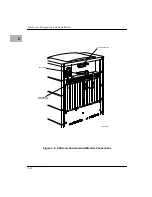
Страница 57: ...Parts List and Ordering Information 5 3 5 Figure 5 1 XR900 Series Chassis 11271 00 9503 1 3 2 4 ...
Страница 58: ...Support Information 5 4 5 ...