


4
4-1
4
Removal/Replacement
Procedures
Introduction
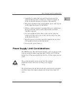
This chapter describes recommended procedures for the removal
and replacement of major assemblies and/or components of the
XR900 chassis. For identification and location of the assemblies and
parts mentioned in these procedures, refer to the drawings and
parts lists in Chapter 6.
The removal/replacement procedures are organized and presented
in the following order:
❏
Front bezel
❏
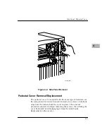
Side panels and pedestal cover
❏
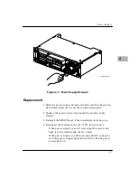
Power supply
❏
Cooling fan
❏
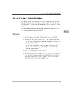
3
1
/
2
- or 5
1
/
4
-inch drive modules
!
Warning
Dangerous voltages, capable of causing death, are
present in this equipment. Use extreme caution when
handling, testing, and adjusting the equipment.
!
Caution
Do not remove power from an operating system
without taking the necessary steps to prevent damage to
the software, the peripherals, or their contents.
Содержание XR900 Series
Страница 1: ...XR900 Series Mass Storage Subsystem User s Manual MCPIOSA UM2 ...
Страница 9: ...x ...
Страница 11: ...xii ...
Страница 43: ...Operating Instructions 3 10 3 ...
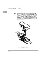
Страница 46: ...Front Bezel 4 3 4 Figure 4 1 Bezel Removal 11051 00 9408 BEZEL LOCKS 1 EACH SIDE LATCH BUTTONS 1 EACH SIDE ...
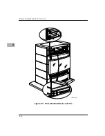
Страница 53: ...Removal Replacement Procedures 4 10 4 Figure 4 4 Drive Module Release Latches 11060 00 9409 ...
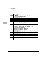
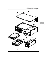
Страница 57: ...Parts List and Ordering Information 5 3 5 Figure 5 1 XR900 Series Chassis 11271 00 9503 1 3 2 4 ...
Страница 58: ...Support Information 5 4 5 ...