


44
August 20, 2003
6809471A67-O
Troubleshooting
V150
b) Earpiece speaker defective.
Remove the transceiver board assembly from
housing and insert into known good front
housing assembly. Ensure good flex connection.
Place a call and verify improvement in earpiece
audio. If fault is cleared, reassemble the phone
with the good front housing assembly. If fault is
not cleared, reinstall into the original housing
and proceed to c.
c) Antenna assembly defective.
Rephase the unit and recheck the symptom. If
symptom is the same but unit rephases
correctly, check to make sure the antenna is
installed correctly. If the antenna is installed
correctly, substitute a known good antenna
assembly. If this does not clear the fault, reinstall
the original antenna assembly and proceed to d.
d) Transceiver board assembly
defective.
Replace the transceiver board assembly (refer
to 1c). Verify that the fault has been cleared and
reassemble with the new transceiver board
assembly.
7. Telephone will not recognize or accept
SIM card.
a) SIM card defective.
Check the SIM card contacts for dirt. Clean if
necessary, and check if fault has been cleared.
If the contacts are clean, insert a known good
SIM card into the telephone. Power up the unit
and confirm that the card has been accepted. If
the fault no longer exists, replace the defective
SIM card. If the SIM card is not at fault, proceed
to b.
b) Transceiver board assembly
defective.
Replace the transceiver board assembly (refer
to 1c). Verify that the fault has been cleared and
reassemble the unit with the new transceiver
board assembly.
8. Phone does not sense when flip is
opened or closed (usually indicated by
inability to answer incoming calls by
opening the flip, or inability to make
outgoing calls).
a) Magnet or reed switch in front
housing assembly defective.
Replace front housing assembly with known
good one. Refer to the procedures. Place call to
phone and verify ability to answer by opening
flip. If fault is cleared, rebuild phone with new
front housing assembly. If fault is still present,
replace original front housing assembly and
proceed to b.
b) Keypad board assembly defective. Replace the keypad board with a known good
one. Place call to phone and verify that the fault
has been eliminated. If not, proceed to c.
c) Transceiver board assembly
defective.
Replace the transceiver board assembly (refer
to 1c). Verify that the fault has been cleared and
reassemble the unit with the new transceiver
board assembly.
9. Vibrator feature not functioning.
a) Vibrator in rear housing assembly
defective.
Replace rear housing assembly. If fault still
present, restore original rear housing assembly
and proceed to b.
b) Transceiver board assembly
defective.
Replace the transceiver board assembly (refer
to 1c). Verify that the fault has been cleared and
reassemble the unit with the new transceiver
board assembly.
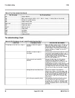
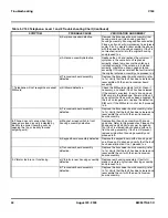
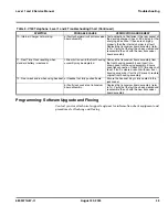
Table 5. V150 Telephone: Level 1 and 2 Troubleshooting Chart (Continued)
SYMPTOM
PROBABLE CAUSE
VERIFICATION AND REMEDY
Содержание V150
Страница 1: ...Level 1 and 2 Service Manual V150 Dual Band Wireless Telephone GSM 900 DCS 1800MHz with GPRS ...
Страница 2: ......
Страница 4: ...4 August 20 2003 V150 ...
Страница 22: ...22 August 20 2003 6809471A67 O General Operation V150 ...
Страница 52: ...Index 4 February 13 2001 6809471A67 O V150 ...
Страница 53: ......