


6809471A67-O
August 20, 2003
35
Level 1 and 2 Service Manual
Disassembly
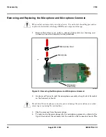
microphone will fit into the board only one way. Ensure the microphone
assembly is fully seated against the PCB.
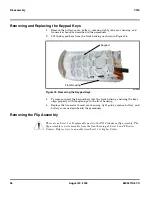
Removing and Replacing the Keypad PCB
1.
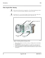
Remove the battery cover, battery, antenna, light guide, rear housing, and
transceiver board as described in the procedures.
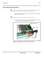
2.
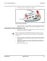
While holding the transceiver board stationary, carefully pull the keypad PCB
straight away from the transceiver board to disconnect as shown in Figure 15.
The disassembly tool may be used to carefully pry the keypad PCB away from
the transceiver board, if necessary.
3.
To replace, align the connector on the keypad PCB with the mating connector
on the transceiver board. Firmly press the two board assemblies together until
the connectors snap into place.
G
Do not force the microphone into its socket. The connector is keyed to fit only one way.
031801o
Figure 15. Removing the Keypad PCB
Keypad PCB Connector
Keypad PCB
Содержание V150
Страница 1: ...Level 1 and 2 Service Manual V150 Dual Band Wireless Telephone GSM 900 DCS 1800MHz with GPRS ...
Страница 2: ......
Страница 4: ...4 August 20 2003 V150 ...
Страница 22: ...22 August 20 2003 6809471A67 O General Operation V150 ...
Страница 52: ...Index 4 February 13 2001 6809471A67 O V150 ...
Страница 53: ......