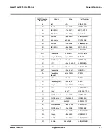


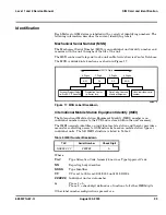


6809471A67-O
August 20, 2003
33
Level 1 and 2 Service Manual
Disassembly
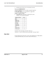
3.
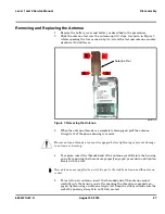
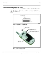
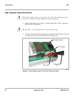
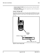
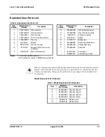
Remove the flex from the ZIF connector to disconnect from the transceiver
board. The Delrin tweezer or EMEA flexprint removal tool may be used to assist
with disconnecting the flex, if necessary, as shown in Figure 12.
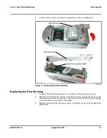
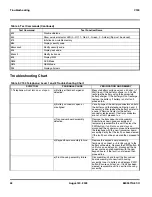
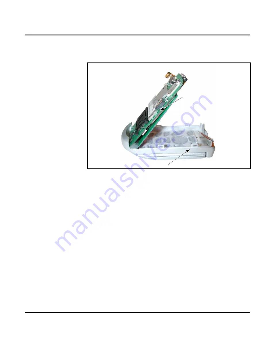
4.
Carefully lift the transceiver board from the front housing as shown in
Figure 13.
Replacing the Transceiver Board
1.
Insert the transceiver board into the front housing with the ZIF connector on
top. Ensure the keypad PCB is properly aligned with the keypad.
2.
Insert the flex squarely into the ZIF connector on the transceiver board and
close the connector latch until it locks into position.
3.
Replace the rear housing, light guide, antenna battery, and battery cover as
described in the procedures.
031733o
Figure 13. Removing the Transceiver Board
G
This product contains static-sensitive devices. Use anti-static handling procedures
to prevent electrostatic discharge (ESD) and component damage.
Transceiver Board
Front Housing
Содержание V150
Страница 1: ...Level 1 and 2 Service Manual V150 Dual Band Wireless Telephone GSM 900 DCS 1800MHz with GPRS ...
Страница 2: ......
Страница 4: ...4 August 20 2003 V150 ...
Страница 22: ...22 August 20 2003 6809471A67 O General Operation V150 ...
Страница 52: ...Index 4 February 13 2001 6809471A67 O V150 ...
Страница 53: ......