


6809471A67-O
August 20, 2003
43
Level 1 and 2 Service Manual
Troubleshooting
2. Telephone exhibits poor reception or
erratic operation such as calls frequently
dropping or weak or distorted audio.
a) Antenna assembly defective.
Check to make sure that the antenna pin is
properly connected to the transceiver board
assembly. If connected properly, substitute a
known good antenna. If the fault is still present,
proceed to b.
b) Transceiver board assembly
defective.
Replace the transceiver board assembly (refer
to 1c). Verify that the fault has been cleared and
reassemble the unit with the new transceiver
board assembly.
3. Display is erratic, or provides partial or
no display.
a) Mating connections to or from
front housing assembly faulty.
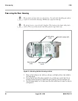
Remove rear housing from unit, check general
condition of flex connector if the flex connector is
good, check that the ZIF connector is fully
pressed down and that the flex collars are flush
with the plastic of the connector.If not, check ZIF
to transceiver board assembly connections. If
faulty connector, replace the transceiver board
assembly. If connector is not at fault, proceed to
b.
b) Front housing assembly defective.
Substitute the good transceiver board assembly
into a known good front housing. If the fault is
cleared, rebuild with new front housing
assembly. If the fault is not cleared, reinstall into
the original front housing assembly and proceed
to c.
c) Transceiver board assembly
defective.
Replace the transceiver board assembly (refer
to 1c). Verify that the fault has been cleared and
reassemble the unit with the new transceiver
board assembly.
4. Incoming call alert transducer audio
distorted or volume is too low.
a) Faulty transceiver board assembly. Replace the transceiver board assembly (refer
to 1c). Verify that the fault has been cleared and
reassemble the unit with the new transceiver
board assembly.
5. Telephone transmit audio is weak.
(usually indicated by called parties
complaining of difficulty in hearing voice).
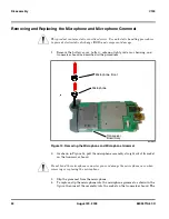
a) Microphone connections to the
transceiver board assembly defective.
Gain access to the microphone as described in
the procedures. Check connections. If connector
is faulty proceed to c; if the connector is not at
fault, proceed to b.
b) Microphone defective.
Gain access to microphone. Disconnect and
substitute a known good microphone. Place a
call and verify improvement in transmit signal as
heard by called party. If good, reassemble with
new microphone. If microphone is not at fault,
reinstall original microphone and proceed to c.
c) Transceiver board assembly
defective.
Replace the transceiver board assembly (refer
to 1c). Verify that the fault has been cleared and
reassemble the unit with the new transceiver
board assembly.
6. Receive audio from earpiece speaker is
weak or distorted.
a) Connections to or from transceiver
board assembly defective.
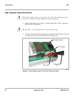
Gain access to the transceiver board assembly
as described in the procedures. Check
connection and the flex from the earpiece to the
transceiver board assembly. If flex is at fault,
replace front housing assembly. If ZIF connector
is at fault, proceed to d. If connection is not at
fault, proceed to b.
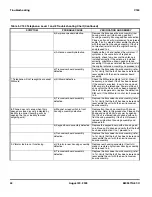
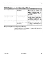
Table 5. V150 Telephone: Level 1 and 2 Troubleshooting Chart (Continued)
SYMPTOM
PROBABLE CAUSE
VERIFICATION AND REMEDY
Содержание V150
Страница 1: ...Level 1 and 2 Service Manual V150 Dual Band Wireless Telephone GSM 900 DCS 1800MHz with GPRS ...
Страница 2: ......
Страница 4: ...4 August 20 2003 V150 ...
Страница 22: ...22 August 20 2003 6809471A67 O General Operation V150 ...
Страница 52: ...Index 4 February 13 2001 6809471A67 O V150 ...
Страница 53: ......