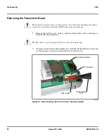

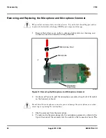

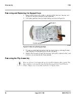


42
August 20, 2003
6809471A67-O
Troubleshooting
V150
Troubleshooting Chart
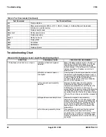
52#
Disable sidetone
54#
Show service indicator LED (0 - Off, 1 - Red, 2 - Green, 3 - Amber) (flip must be closed)
57#
Initialize non-volatile memory
58#
Display security code
58xxxxxx#
Modify security code
59#
Display lock code
59xxx#
Modify lock code
60#
Display IMEI
980#
DCS Mode
981#
GSM Mode
99#
Display all pixels
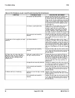
Table 5. V150 Telephone: Level 1 and 2 Troubleshooting Chart
SYMPTOM
PROBABLE CAUSE
VERIFICATION AND REMEDY
1. Telephone will not turn on or stay on.
a) Battery either discharged or
defective.
Measure battery voltage across a 50 ohm (>1
Watt) load. If the battery voltage is <3.25 Vdc,
recharge the battery using the appropriate
battery charger. If the battery will not recharge,
replace the battery. If battery is not at fault,
proceed to b.
b) Battery connectors open or
misaligned.
Visually inspect the battery connectors on both
the battery and the telephone. Realign and, if
necessary, either replace the battery or refer to
a Level 3 Service Center for the battery
connector replacement. If battery connectors
are not at fault, proceed to c.
c) Transceiver board assembly
defective.
Remove the transceiver board assembly.
Substitute a known good assembly and
temporarily reassemble the unit. Depress the
PWR button; if unit turns on and stays on,
disconnect the dc power source and reassemble
the telephone with the new transceiver board
assembly. Verify that the fault has been cleared.
If the fault has not been cleared then proceed to
d.
d) Keypad board assembly failure.
Replace the keypad board assembly.
Temporarily connect a +3.6 Vdc supply to the
battery connectors. Depress the PWR button. If
unit turns on and stays on, disconnect the dc
power source and reassemble with the new
keypad board. If the fault is not cleared then
proceed to e.
e) Front housing assembly failure.
Disassemble unit and insert the transceiver
board assembly into new front housing
assembly. Insert a battery and depress PWR
button. Ensure unit stays on. If fault has been
cleared, reassemble unit in new front housing
assembly.
Table 4. Test Commands (Continued)
Test Command
Test Function/Name
Содержание V150
Страница 1: ...Level 1 and 2 Service Manual V150 Dual Band Wireless Telephone GSM 900 DCS 1800MHz with GPRS ...
Страница 2: ......
Страница 4: ...4 August 20 2003 V150 ...
Страница 22: ...22 August 20 2003 6809471A67 O General Operation V150 ...
Страница 52: ...Index 4 February 13 2001 6809471A67 O V150 ...
Страница 53: ......