


6809471A67-O
August 20, 2003
29
Level 1 and 2 Service Manual
Disassembly
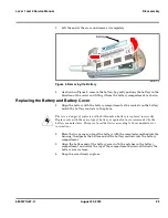
2.
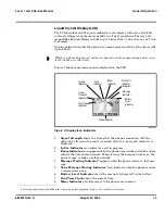
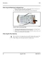
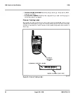
As shown in Figure 9 (A), align the right side of the removal tool with the lip
of the battery compartment.
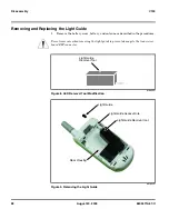
3.
As shown in Figure 9, carefully insert the tip of the removal tool (B) into the
light guide access hole near the top of the rear housing.
4.
Gently push the shaft of the tool straight into the housing until resistance is
felt. Observe the depth as indicated by the mark on the tool.
5.
If resistance is felt at a depth of 9.6 mm or less, as indicated by the depth mark
on the tool, the tool has contacted the edge of the transceiver board ZIF
connector. Raise the tool slightly to clear the connector.
6.
Resistance felt at a depth greater than 9.6 mm means the tool is clear of the
ZIF connector and has properly contacted the light guide.
7.
When the tool is in contact with the light guide, carefully push to expose the
light guide enough to grasp with pliers for removal from the housing.
8.
To replace, insert the light guide straight into the opening in the top of the rear
housing and push until fully seated.
Содержание V150
Страница 1: ...Level 1 and 2 Service Manual V150 Dual Band Wireless Telephone GSM 900 DCS 1800MHz with GPRS ...
Страница 2: ......
Страница 4: ...4 August 20 2003 V150 ...
Страница 22: ...22 August 20 2003 6809471A67 O General Operation V150 ...
Страница 52: ...Index 4 February 13 2001 6809471A67 O V150 ...
Страница 53: ......